


Part Number: TMS320F2800132
Tool/software:
[Since a partnumber is required but TMS320F240PQA is not in the list I selected most similar being TMS320F2800132]
I'm doing a repair of a PCB where the TMS320F240PQA is defect.
GOAL: I want to be able to download a backup I have into a new soldered chip.
I already read quite some forum threads and learned the following:
- It's a very old DSP chip, obsolete. It has no readout security
- Reading can be done on a windows XP with CCS3.3 using a XDS510-USB2.0 TI DSP EMULATOR ( ran in a virtual machine ) by going 'File' -> 'Data' -> 'Save' and store from address 0x0000 a length of 0x8000 bytes in a coff format (.out) -> I have done this successfully

- Writing can not be done with CCS 3.3 (correct me if I am wrong)
- Writing can not be done with my XDS510-USB2.0 TI DSP EMULATOR (correct me if I am wrong)
- Writing should be done with the DOS program Prg2xx
- Writing can be done with the XDS510 ISA controller card connected to a Spectrum digital XDS510PP plus

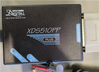
I bought myself an old PC with win98 and an ISA slot. Inserted the card. In BIOS I reserved some IRQ's for ISA legacy devices. I attached the XDS510PP and fed it with 5V.
The XDS510PP plus is fysically connected to the PCB with the foreseen header. The board is powered.
I run C:\specdig\prg2xx\f240\BTEST.bat and get "API Error 100" This readme file explains this error as "Target power detected, but scan path is not functional" 6011.README.PDF
Unfortunately I get this same error when no adapter is attached so it doesn't confirm a correct connection to the XDS510PP plus.
Then there is this F240 file, both files tell me the internal clock should run at 20Mhz, there is a CLKOUT pin on this chip which I measured, for one device this is good (20Mhz) for another this is 8Mhz. I Attached a signal generator at CLKIN to bump the clockspeed at CLKOUT but it collapses at 18Mhz. There is some explanation on how to reconfigure the PLL for me its a contradiction: connecting to the chip requires 20mhz internal clock but reconfiguring the pll requires you to have a connection (to change the settings)?
VCCP is 5V and the chip is in MC mode (MP /MC pin LOW).
In SDConfig using emulator test on '240' I get:

Also I would expect the 'Active' led on the XDS510PP plus to turn on but it is off.
Really hoping someone can help me out by clearing out some of the questions I have or pointing me to the fault I'm currently making 

General Questions I have:
- How do I need to set the DIP switches of this ISA card
- How to install the XDS510 ISA card, do I need to install drivers?
- How to get the chips internal clock to 20Mhz
- When does the active led of the XDS510PP theoretically go on.
- Is my setup currently able to communicate with the XDS510PP or not?
