This thread has been locked.

If you have a related question, please click the "Ask a related question" button in the top right corner. The newly created question will be automatically linked to this question.

TMS320F2800156-Q1: MCAN example in bitfield Format

Part Number: TMS320F2800156-Q1

Tool/software:

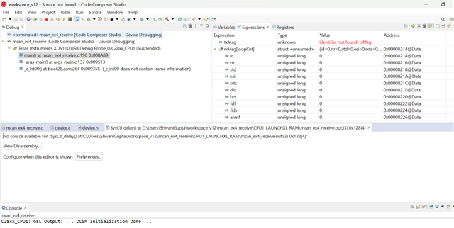
I am currently working on the F2800156-Q1 (32-pin) microcontroller for a PMSM controller project. We are developing the code using the bitfield format. I have configured Pin 27 (GPIO1) as MCAN_TX and Pin 28 (GPIO0) as MCAN_RX. However, I am unable to find the any MCAN example code in bitfield format. Please share any MCAN example code for C2000 controller.

  • Hi Shivani,

    Unfortunately, there are no bitfield examples on MCAN at this point.  The bitfield headers are available but in general, all software examples are released in driverlib format in C200Ware.

    Regards,

    Joseph

  • Hi Joseph 

    Thank you for your response.           

    I am also trying to utilize the Driver-lib example mcan_ex1_loopback  for TMS320F2800156. however, I am unable to detect any CAN output using either the PCAN tool or an oscilloscope. I have modified both the GPIO configurations  (Pin 27 (GPIO1) as MCAN_TX and Pin 28 (GPIO0) as MCAN_RX) and the CAN clock settings according to my requirement. Additionally, I tested the similar example (mcan_ex1_loopback) on the LAUNCHXL-TMS320F28P550SJ9,  only GPIO pin modification is done here( GPIO4 as MCAN_TX and  GPIO5 as MCAN_RX), but no output was observed there either. 

    Regards

    Shivani Gupta

  • Hi Shivani,

    If you are using the LaunchPad for either F2800156 or F28P550SJ9, the GPIOs that are physically connected to the transceiver and the CAN terminals CANL/CANH are GPIO4 and GPIO5.  Other GPIOs will not work since they will not be connected to the on board CAN transceiver.

    In addition, confirm that switch s4 is set to the correct position so GPIO4/5 will be connected to the transceiver.

    mcan_ex1_loopback is configured with bit rate switching and that NOM rate is 500kbps and DATA rate is 1Mbps.  Ensure in the PCAN setup that bit rate switching is enabled and it will match the NOM and DATA rates configured in the example.

    Regards,

    Joseph

  • Hi Joseph , 

    I am using Launch Pad of F28P559SJ9-Q1 microcontroller, I have set the GPIO4 & GPIO5 as MCANA_TX & MCANA_RX by changing device.h file.

      // Configuring the GPIOs for MCAN.
    GPIO_setPinConfig(DEVICE_GPIO_CFG_MCANRXA);
    GPIO_setPinConfig(DEVICE_GPIO_CFG_MCANTXA); 

    I have not done any changes in c2000.syscfg file. Please assist me if any change need to be done in  c2000.syscfg.

    Additionally  switch s4 is set to the correct position so GPIO4/5 is connected to the transceiver. PCAN tool setting is also done correctly.

  • Hi Shivani,

    Yes, that is the correct set of GPIOs for the MCAN transceiver.  I did some bit timing calculations and you should actually be using a 500kbps NOM rate and 2Mbps DATA rate for the test case that you are using.  Can you check this out on your PCAN setup?

    Thanks,

    Joseph

  • Hi Joseph, 

    I am sharing the PCAN detail with you. Please look into it. My issue is still there, even i have change the configuration from CAN FD to classic CAN still it is not working. 

    I also did the bit timing calculation please verify it.

    The SYSCLK = 150MHz, MCAN_bit_clock = 150MHz/5 = 30MHz.

    Nominal bit rate - 

    NOM_BRP =11, TQ=(BRP+1)/30MHz = 400ns , NOM_Bit rate = 1/(Tseg1+Tseg2+1)*TQ => 500kb/s = 1/400ns *(Tseg1+Tseg2+1) =>(Tseg1+Tseg2+1) = 5, as per code Tseg1 =2 +1, Tseg2=0 +1 ( I am assuming 1TQ is subtracted from both & 1TQ is fixed for sync_seg).

    Same logic i have applied for data bit rate  Data_BRP =1, TQ for data =(BRP+1)/30MHz = 66.66ns , Data_Bit rate = 1/(Tseg1+Tseg2+1)*TQ => 2Mb/s = 1/66.66ns *(Tseg1+Tseg2+1) =>(Tseg1+Tseg2+1) = 7.5, as per code Tseg1 =10 +1, Tseg2=2+1 ( I am assuming 1TQ is subtracted from both & 1TQ is fixed for sync_seg), but not matching as per calculation. 

    I have tried another bit timing parameters but still not working.

    Even I have tried two more  Driver-lib examples mcan_ex4_receive and mcan_ex9_transmit, these two are also not working.

    Can you share any working MCAN example with me?

  • Hi Shivani,

    I'm looking for a F28P55x set up to try the examples out myself.  Hopefully I can get to this by mid of this week.

    Regards,

    Joseph 

  • Thank you Joseph, 

    I am waiting for your response.

    Regards,

    Shivani

  • Hi Shivani,

    Earliest that I will have the F28P55x LaunchPad will be tomorrow so I will not have an update for you today.

    Regards,

    Joseph

  • Hi Joseph,

    No Problem, when you are done with verifying P55 example setup, please update.

    Regards,

    Shivani.

  • Hi Shivani,

    I tested mcan_ex9_transmit as it is with the modification of MCANTX/TX pins to GPIO4/5 and got it to work.  Here are the settings used for bit timings:

        //
        // Initialize bit timings.
        //
        bitTimes.nomRatePrescalar   = 0xBU; // Nominal Baud Rate Pre-scaler
        bitTimes.nomTimeSeg1        = 0x2U; // Nominal Time segment before SP
        bitTimes.nomTimeSeg2        = 0x0U; // Nominal Time segment after SP
        bitTimes.nomSynchJumpWidth  = 0x0U; // Nominal SJW
        bitTimes.dataRatePrescalar  = 0x1U; // Data Baud Rate Pre-scaler
        bitTimes.dataTimeSeg1       = 0xAU; // Data Time segment before SP
        bitTimes.dataTimeSeg2       = 0x2U; // Data Time segment after SP
        bitTimes.dataSynchJumpWidth = 0x2U; // Data SJW
    
    MCAN Clock = 150MHz/5 = 30MHz
    
    Nom rate = (30MHz/(0xB + 0x1))/(Tseg1 + Tseg2 +3) = 2.5MHz/(2+0+3) = 500kbps
    Data rate = (30Mhz/(0x1 + 0x1)/(Tseg1 + Tseg2 +3) = 15MHz/(10+2+3) = 1Mbps


    Also tested with dataRatePrescalar  = 0, which is 2Mbps data rate and I'm seeing successful transaction.  See below snippet:

    Can you step through your code to see if the test case executes to the end of the test?  Test may be failing somewhere else.

    Regards,

    Joseph

  • Hi Joseph thank you so much for your assistance. 

    I am trying it, just provide some time. 

    Regards, 

    Shivani 

  • Hi Shivani,

    Ok, understood.

    Regards,

    Joseph

  • Hi Joseph,

    Thank you for your patience & assistance

    I have tried  examples of F28P55x on Launchpad, they are working fine, I got the output on PCAN tool, I have figured out the this issues & applied the change accordingly on setting as shown below.

    The PCAN tool output 

    But when I have tried the same example on F2800156Q1 (Since I don't have launch pad for F2800156Q1 ), I have directly applied on my project but the code (mcan_ex4_receive.c) gets struck at this point 

    After resuming it 2-3 time the code again run but no output, when I pause it it is showing this message. Also I want to mention one important point that till now i did not turn on external crystal oscillator for my project.

    Regards, 

    Shivani

  • One important thing to mention that my crystal oscillator is damage, Can I run MCAN using internal oscillator?

  • Hi Shivani,

    For checking out the functionality and as long as the baud rate and CAN bus length are kept at a minimum, using the internal oscillator should work.  In actual application though, where CAN bus can be as long as a few feet and environment is noisy, precision clock source is  required to meet the stringent CAN timing requirements.  With the internal oscillator, you need to ensure that SYSCLK is still configured at 120MHz for the example to work.

    The error trap that you are running into can be caused by several issues though.  You can step through the code while you are in debugger/emulation mode in Code Composer so you can trace exactly where the error is happening.

    Regards,

    Joseph

  • Thank you so much for your assistance Joseph,

    I am getting the output after using external crystal oscillator, using only internal oscillator it was not working. I think MCAN requires two clock source.