Tool/software:
I designed a board including external memory on EMIF2 copying the F28379D_EMIF_DC reference design.
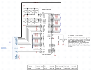
The SDRAM is configured with the following code:
void configure_sdram() {

    // Do not synchronize the EMIF2 pins
    for (unsigned i = 53; i <= 68; i++) {
        GPIO_setPadConfig(i, GPIO_PIN_TYPE_PULLUP);
        GPIO_setQualificationMode(i, GPIO_QUAL_ASYNC);
    }

    GPIO_setPinConfig(GPIO_68_EMIF2_D0);
    GPIO_setPinConfig(GPIO_67_EMIF2_D1);
    GPIO_setPinConfig(GPIO_66_EMIF2_D2);
    GPIO_setPinConfig(GPIO_65_EMIF2_D3);
    GPIO_setPinConfig(GPIO_64_EMIF2_D4);
    GPIO_setPinConfig(GPIO_63_EMIF2_D5);
    GPIO_setPinConfig(GPIO_62_EMIF2_D6);
    GPIO_setPinConfig(GPIO_61_EMIF2_D7);
    GPIO_setPinConfig(GPIO_60_EMIF2_D8);
    GPIO_setPinConfig(GPIO_59_EMIF2_D9);
    GPIO_setPinConfig(GPIO_58_EMIF2_D10);
    GPIO_setPinConfig(GPIO_57_EMIF2_D11);
    GPIO_setPinConfig(GPIO_56_EMIF2_D12);
    GPIO_setPinConfig(GPIO_55_EMIF2_D13);
    GPIO_setPinConfig(GPIO_54_EMIF2_D14);
    GPIO_setPinConfig(GPIO_53_EMIF2_D15);

    GPIO_setPinConfig(GPIO_97_EMIF2_DQM0);
    GPIO_setPinConfig(GPIO_96_EMIF2_DQM1);

    GPIO_setPinConfig(GPIO_98_EMIF2_A0);
    GPIO_setPinConfig(GPIO_99_EMIF2_A1);
    GPIO_setPinConfig(GPIO_100_EMIF2_A2);
    GPIO_setPinConfig(GPIO_101_EMIF2_A3);
    GPIO_setPinConfig(GPIO_102_EMIF2_A4);
    GPIO_setPinConfig(GPIO_103_EMIF2_A5);
    GPIO_setPinConfig(GPIO_104_EMIF2_A6);
    GPIO_setPinConfig(GPIO_105_EMIF2_A7);
    GPIO_setPinConfig(GPIO_106_EMIF2_A8);
    GPIO_setPinConfig(GPIO_107_EMIF2_A9);
    GPIO_setPinConfig(GPIO_108_EMIF2_A10);
    GPIO_setPinConfig(GPIO_109_EMIF2_A11);
    GPIO_setPinConfig(GPIO_95_EMIF2_A12);

    GPIO_setPinConfig(GPIO_111_EMIF2_BA0);
    GPIO_setPinConfig(GPIO_112_EMIF2_BA1);
    GPIO_setPinConfig(GPIO_113_EMIF2_CAS);
    GPIO_setPinConfig(GPIO_114_EMIF2_RAS);
    GPIO_setPinConfig(GPIO_115_EMIF2_CS0N);
    //GPIO_setPinConfig(GPIO_110_EMIF2_WAIT);
    //GPIO_setPinConfig(GPIO_116_EMIF2_CS2N);
    GPIO_setPinConfig(GPIO_117_EMIF2_SDCKE);
    GPIO_setPinConfig(GPIO_118_EMIF2_CLK);
    //GPIO_setPinConfig(GPIO_119_EMIF2_RNW);
    GPIO_setPinConfig(GPIO_120_EMIF2_WEN);
    //GPIO_setPinConfig(GPIO_121_EMIF2_OEN);

    SysCtl_setEMIF2ClockDivider(SYSCTL_EMIF2CLK_DIV_2);
    SysCtl_configureType(SYSCTL_MEMMAPTYPE, 0x1U, 0x1U);

    // Allow CPU and DMA access to EMIF2
    EMIF_setAccessProtection(EMIF2CONFIG_BASE, 0x0);
    EMIF_commitAccessConfig(EMIF2CONFIG_BASE);
    EMIF_lockAccessConfig(EMIF2CONFIG_BASE);

    // Apply timing parameters
    EMIF_SyncTimingParams syncTimingParams;
    syncTimingParams.tRfc = 6; // Refresh to Active/Refresh command delay
    syncTimingParams.tRp  = 1; // Precharge to Activate delay
    syncTimingParams.tRcd = 1; // Activate to Read/Write delay
    syncTimingParams.tWr  = 2; // Write recovery time
    syncTimingParams.tRas = 4; // Active to Precharge delay
    syncTimingParams.tRc  = 6; // Active to Active/Auto Refresh delay
    syncTimingParams.tRrd = 1; // Activate to Activate delay (different banks)
    EMIF_setSyncTimingParams(EMIF2_BASE, &syncTimingParams);

    // Set the self-refresh timing (often 64 ms, but here 7.8 us)
    EMIF_setSyncSelfRefreshExitTmng(EMIF2_BASE, 0x7U);
    EMIF_setSyncRefreshRate(EMIF2_BASE, 781); // 7.81 us

    // Configure structure for EMIF2
    EMIF_SyncConfig syncConfig;
    syncConfig.casLatency = EMIF_SYNC_CAS_LAT_2;
    syncConfig.iBank = EMIF_SYNC_BANK_4;
    syncConfig.narrowMode = EMIF_SYNC_NARROW_MODE_TRUE; // 16-bit mode
    syncConfig.pageSize = EMIF_SYNC_COLUMN_WIDTH_9;

    EMIF_setSyncMemoryConfig(EMIF2_BASE, &syncConfig);
}
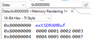
Using this test function I noticed a weird behavior:
__attribute__((far)) volatile uint16_t sdram_buffer[8];
volatile uint16_t buffer[8] = {0};
volatile bool error_sdram = 0;
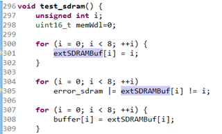
void test_sdram() {
for (unsigned i = 0; i < 8; ++i) {
sdram_buffer[i] = i;
}
for (unsigned i = 0; i < 8; ++i)
error_sdram |= sdram_buffer[i] != i;
for (unsigned i = 0; i < 8; ++i) {
buffer[i] = sdram_buffer[i];
}
}
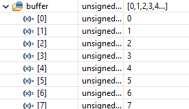
The values in `buffer` are:
1, 1, 3, 3, 5, 5, 7, 7
I noticed from SPRAC96A :
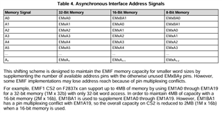
In which we have a shift for 16-bit memory.
What is the correct way? F28379D_EMIF_DC with the 16-bit SDRAM or Table 4 from SPRAC96A?
I would like to find the best way to fix my design or the code.