This thread has been locked.

If you have a related question, please click the "Ask a related question" button in the top right corner. The newly created question will be automatically linked to this question.

TMS320F28069: Multi Duty PWM pulse through single GPIO

Part Number: TMS320F28069

Tool/software:

Hi,

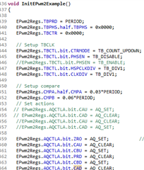
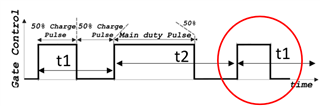
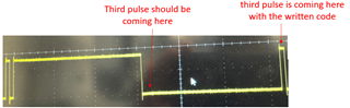
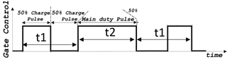
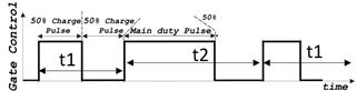
I wanted to create a continuos PWM signal with two different duties as shown below through just one GPIO. The first pulse has let's say has a switching period of t1 and the second pulse has t2 where t1<t2.  I was wondering if you had any suggestions. Since there is limited CAU, CBU, ZRO and PRD commands. I am getting stuck.

Regards,

Sourish 

  • Hi Sourish,

    To clarify, it sounds like the concern is that you are limited in the number of events that can be used to generate PWM edges. 

    Have you tried using up-down count mode on this device? You can generate different actions on events:

    • CTR = 0
    • CTR = CMPA counting up
    • CTR = CMPB counting up
    • CTR = PRD
    • CTR = CMPB counting down
    • CTR = CMPA counting down

    Best Regards,

    Allison

  • Hi, I tried your suggestion. I am pasting the code below. However, the third pulse i.e. the one shown on the red circle is not where I want it to be with the code.

    My oscilloscope result is this:

    As you can see I need the pulse closer to the second pulse.

    Regards,

    Sourish

  • Hi Sourish,

    Can you check your CMPA, CMPB, and PRD values in the registers window and ensure these values are the expected values based on your calculations? If you are updating these values, I'd recommend keeping them static at first so you can check that your configurations are correct before adjusting loading configurations etc.

    Best Regards,

    Allison

  • Hi Allison,

    Yes, I did check those values, and they are what I need.  I am not updating the CMPA and CMPB values in any separate ISR for the moment (before I get the fixed value based code working).

    One small thing, I made a mistake in my timing denotation in my previous plots. t2 for the second pulse and t1 for the third pulse would look like as shown in the image below. Ofcourse this does not change the coding flow. But this updated image kind of tells you that the third pulse must start immediately after the second with a small delay. 

    Additionally, are there more advanced TI C2000 series Microcontrollers which support more comparators in the action qualifier block to generate PWM's? All of those that I know of only support two (CMPA and CMPB) in the AQ block. CMPC and CMPD are still not included in the AQ block in the controllers like 280049 or 28379. Thus, I cannot use them to generate these variable duty cycles through the same GPIO. 

  • Hello Sourish,

    Yes, newer devices have much more flexibility in creating complex waveforms. Please take a look at F28P65x. This device has a new EPWM type (Type-5) and should easily be able to accommodate this waveform. You can check out simple descriptions of type 5 features HERE Slight smile

    Best Regards,

    Allison

  • Hi Allison,

    Got it, I will look into the F28P65z. Just a quick query though. So, am I correct to assume that C2000 series microcontrollers do not have the capability to generate the waveform pattern that I mentioned above?

    Regards,

    Sourish

  • Hi Sourish,

    To clarify, F28P65x is a part of the C2000 series, which encompasses all C28 CPU and C29 CPU-based MCUs Blush. If you are trying to implement this PWM scheme only using the hardware CMPA/B counter compare events and within a single PWM period, I do not see a very direct path for the specific values you described.

    The type 5 EPWM features target more complex waveforms with many sets of, so I would suggest moving to a newer C2000 if you are able. The list of devices and their peripheral types can be seen here: https://www.ti.com/lit/ug/spru566t/spru566t.pdf. Is there a specific reason you are using an older generation C2000 device?

    Best Regards,

    Allison