This thread has been locked.

If you have a related question, please click the "Ask a related question" button in the top right corner. The newly created question will be automatically linked to this question.

TMDSCNCD28P65X: F28P65 - load program into flash and run in standalone mode

Part Number: TMDSCNCD28P65X
Other Parts Discussed in Thread: TMDSHSECDOCK, C2000WARE

Tool/software:

Hi

I'm using TMDSCNCD28P65 control card with TMDSHSECDOCK docking station to import the example project: epwm_ex1_trip_zone from C2000Ware_DigitalPower_SDK_5_03_00_00.


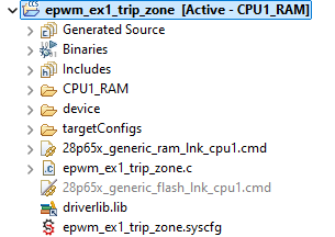
The default of example project is programing to RAM. Since I want to load the program into flash so that I can run without entering debug mode via CCS. I set the CPU1_FLASH as ACTIVE.

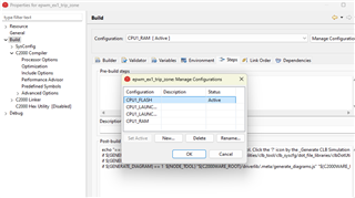
Then I re-Build the project and load it. Under the CCS Debug mode window, this code was good and the PWM has output.

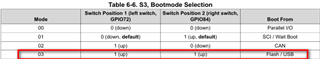
But once I terminate it and re-power on the control card and docking station without entering CCS debug mode, it won't generate PWM output. Even configure S1 pin1 & 2 as OFF, it won't generate PWM.

Is there any configuration I missed or any setup that is not correct?

Thanks.

Jerry.

  • Hi Jerry,

    It sounds like you've done most of the steps correctly. Here are a few things to check:

    1. Boot Mode Configuration: Ensure that the boot mode pins (S1 pin1 & pin2) are correctly configured for booting from FLASH. Double-check the control card's documentation to confirm the correct settings.

    2. Linker Command File: Verify that the linker command file is correctly set up for FLASH. The memory sections should be mapped to FLASH instead of RAM.

    3. Initialization Code: Make sure that any necessary initialization code (such as setting up the PLL, watchdog, etc.) is included in the code that runs from FLASH. Sometimes, code that works in RAM might miss some initialization steps required for FLASH.

    4. Copying Code to RAM: If your application requires certain functions to run from RAM for speed reasons, ensure that the code is correctly copied from FLASH to RAM at runtime.

    5. Entry Point: Ensure that the entry point of your application is correctly set up in the linker command file and that the reset vector points to the correct start address in FLASH.

    6. Flash API: If you are using any Flash API functions, ensure they are correctly linked and called.

    If all these settings are correct and the issue persists, you might want to compare your project settings with the example project provided by TI for FLASH mode to ensure there are no discrepancies.

    Regards, Deep

  • Hi Jerry,

    Can you confirm your HW setup is set to boot from flash. Since you are using a controlCARD, you will need to cross reference the switches on the controlCARD are set to boot to flash. See the controlCARD documentation in C2000Ware ( see section 4.3 in https://www.ti.com/lit/ug/spruj90b/spruj90b.pdf )

    Please note the C2000Ware examples should build out of the box.

    Regards,

    Ozino

  • Hi Deep

    Thanks for your reply and your suggestions. That helped me a lot!!

    I've found out that I missed S3 switch. After confirmed with TMSCNCD28P65x information guide, S3 switch should be set as follows:

    Then power on (without CCS debug mode), the code can run and generate PWM output.

    Regards.

    Jerry

  • Awesome. Glad to hear it Jerry thanks for the feedback and happy coding Slight smile

    Regards,

    Ozino