This thread has been locked.

If you have a related question, please click the "Ask a related question" button in the top right corner. The newly created question will be automatically linked to this question.

TMS320F2800157: Debugging I2C boot mode

Part Number: TMS320F2800157
Other Parts Discussed in Thread: C2000WARE

Tool/software:

I have a F280015x Series LaunchPad and I want to verify my code that will boot in an I2C EEPROM at address 0x50. According to the TRM, I can connect the EEPROM on GPIO4 & GPIO5 and these can be set in the OTP as 0x47 when I finally complete my design.

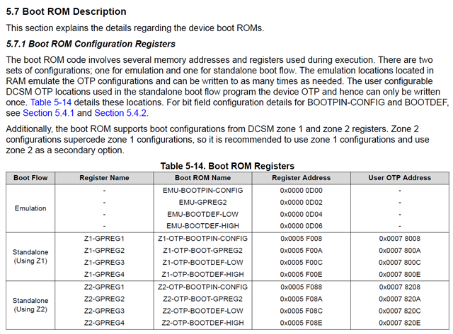
I'm not seeing an explanation on how to invoke the debugger and setting EMU-BOOTPIN-CONFIG.  I found this reference that follows, but not seeing how to configure CCS 20. 

CCS/LAUNCHXL-F280049C: Set EMU-BOOTPIN-CONFIG / EMU-BOOTDEF instead of OTP - C2000 microcontrollers forum - C2000Tm︎ microcontrollers - TI E2E support forums

If I start a debug session and open the Watch window, I don't get any options - just a blank box.  Additionally, Reset offers two options 1) CPU and 2) System. After choosing either, the CPU is halted, and I don't see how to restart it.

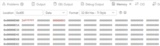
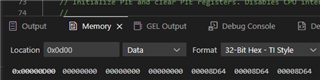
Once you are connected to device via CCS, open the address location in CCS memory watch window and update the value as needed. After setting the values, issue reset from CCS and now when you click on "Run", device will boot as per the emulation boot settings.

Thanks for your advice in advance.

John

  • Hi John,

    I believe those instructions are referring to using the "Memory" view ("Memory Browser" in older versions of CCS). That window should allow you to enter the address of the EMU boot config registers and modify them.

    I don't think the type of reset will make a difference. To start running after the reset, you should be able to hit the "Continue" button (or go to Run -> Continue). Is that not working for you?

    Whitney

  • Hi Whitney,

    I'm quite a newbie at CCS 20 but was able to get out of halt.  How to I set EMU-BOOTPIN-CONFIG at the start of the program so I can boot from I2C?

    John 

  • Hi Whitney,

    I think I'm on to the Rosetta Stone in the TRM that links all of this together. Below is the page in the TRM that shows the actual register that needs to be changed in the debugger are the Zx-GPREGx registers.

    Below is the view in the Register panel that provides access.

    I will try this out next week, so I ask that we leave the support request open until then.

    John

  • Right, those "EMU" fields at 0xD00 are the ones you'll be writing to test the bootloader while debugging. I don't think we have them viewable in the Registers view unfortunately (unlike the OTP fields you showed in your post). Like I mentioned though, using the Memory window should work fine.

    In the image above, went to Scripts -> Emu Boot Load Select -> EMU_BOOT_FLASH just to populate the EMU boot config section to make it a little easier to visualize the settings.

    At address 0xD00, the value 0x5AFFFFFF basically says to ignore the BMSPs and use boot mode 0 in the BOOTDEF table. Then at address 0xD04, it assigned Flash (3) to boot mode 0 in the BOOTDEF table. If you run EMU_BOOT_RAM, the 3 will turn to 5. This is where you can write that 0x47 value you mentioned earlier to select I2C on GPIO5 and GPIO4.

    Whitney

  • Hi Whitney,

    Had to push trying this out to next week to support some internal issues.  Please keep this open until then.

    John

  • That's fine. I will keep it open and threads won't automatically lock until after 30 days of no new replies.

    Whitney

  • Hi Whitney,

    Wanting to keep this thread open as I've been fighting an IT issue with CCS and developing my PROM image.

    Thanks,

    John

  • Hi John--No problem. I won't close it.

    Whitney

  • Hi Whitney,

    Having difficulties booting the I2C EEPROM.

    I'm using the 157LaunchPad and have three different variants of an LED blinking program so I can determine which program is running.  There's one loaded in the TMS320 Flash, my CCS copy that I startup debug with has the second and the I2C EEPROM has the third.   The CCS copy runs from RAM so it doesn't overwrite the copy that is in Flash. 

    If I run my CCS based program, I see it blink the LEDs in the expected sequence.  If I pause it and look at memory, I don't see the patterns you showed earlier. 

    If I run the EMU_BOOT_FLASH or EMU_BOOT_RAM scripts I do see the memory values change at these locations.  I was expecting to see them already in place so when I ran my code, I could just pause, write the 0x47 in at the 0xD04 location, reset CPU, run, and see my I2C code boot.  

    Can you help put me back on track?

    John

  • I don't think they're usually populated by default. I think it's normal to have to write them yourself (or using the GEL file scripts).

    But you are right about the next steps. Once the EMU Boot settings are in place, you should be able to reset and run. What is happening when you try that? Is it getting stuck somewhere? Is it booting to Flash instead?

    You should be able to add the boot ROM symbols to your debug session (Run -> Load -> Add symbols) and debug the boot ROM like you would your own code.

    If you haven't done that before, you can find the symbols .out in the folder below:

    <C2000Ware>\libraries\boot_rom\f280015x\rev1\rom_sources\ccs_files\cpu\Release

    And when CCS asks you to locate the source files, you can direct it to

    <C2000Ware>\libraries\boot_rom\f280015x\rev1\rom_sources\F280015x_ROM\bootROM\source

    I'd use the Disassembly view to put a breakpoint in the CPU1BROM_startSystemBoot() (in cpubrom_boot.c) and then step through that code.

    Whitney

  • Hi Whitney,

    You are correct that my system is booting to Flash.

    I agree with the direction you are pointing me to and I'm attempting to get there.  Here's where I'm at. 

    I started my base program in Debug and allowed it to load to RAM.  I go to <C2000Ware>\libraries\boot_rom\f280015x\rev1\rom_sources\ccs_files\cpu\Release and find two .out files: F280015x_CPU1_Full_ROM.out and F280015x_ROM.out.  If I load F280015x_CPU1_Full_ROM.out I get an error finding a .asm file.  Loading F280015x_ROM.out seems to be ok.

    I run the Scripts -> Emu Boot Load Select -> EMU_BOOT_FLASH and set BOOT MODE to 47.

    I open <C2000Ware>\libraries\boot_rom\f280015x\rev1\rom_sources\F280015x_ROM\bootROM\source\cpubrom_boot.c and set a breakpoint at line 2075

    I get No code associated with any symbols loaded.  Included a screenshot that I hope will help.

    Thanks again for your coaching!

    John

  • Hi Whitney,

    I have managed to see that I can startup my debug program and after running it once, I can change the BOOT MODE from 5 to 3 and boot the copy in FLASH.  I've also seen mode 5 causing the memory copy to be executed.

    I've set to BOOT MODE 47, but can't see where it's going because I'm still missing how to debug through the bootloader code.

    Have found a few posts talking about debugging through the bootloader, but no real insight on loading the symbol file, setting a breakpoint, and stepping through it.  Are there TI documents that cover this?

    I will keep digging until I hear from you.

    John

  • Hi John,

    Sorry, I should have tried this in CCS 20 first since it doesn't seem to handle to locating of source code quite as nicely.

    After adding symbols, I was able to open the disassembly window and look up the CPU1BROM_startSystemBoot function and place a breakpoint to run to it.

    Unlike older CCS versions, this didn't seem to trigger CCS to ask me to locate source. However, I was able to go to Run -> Edit Source Paths... and add the ROM source folder to the list.

    This still didn't allow me to single-step through the C code, but it seems to have given CCS enough of a link between the cpubrom_boot.c file and the ROM symbols to allow me to put breakpoints in the C code and run to them. For example, I put a breakpoint in the RAM_BOOT case, ran the EMU_BOOT_RAM script, resumed the application, and saw it hit the breakpoint.

    It's not ideal, but it's what I was able to work out this afternoon. You could ask on the CCS forum if they have any tips to make it better. This was the only mention of it in the documentation I could find:

    software-dl.ti.com/.../ccs_debug-main.html

    Whitney

  • Hi Whitney,

    I followed your post which allowed me to see that I was trying to access the I2C prom, but only the prom header was read (scope trace).  Found out I didn't have any of the clock registers set.  Setting those was the issue.

    Thanks so much for teaching me how to debug through the bootrom. Will definitely hold on to this for the future.

    John