Other Parts Discussed in Thread: SYSCONFIG, C2000WARE
Tool/software:
Hi,
I have a program that receives a command through SCI from both CPUs and echos that on both CPUs. So I could see if the CPUs reset/restart on two terminals.
I am using "Delfino TMS320F28379D control CARD R1.3". I have not been able to run this program after a power cycle without starting a debug session. Here are the steps I take and tried. When I mention multiple options in one step it means I've tried all the permutations of these steps with the combinations listed.
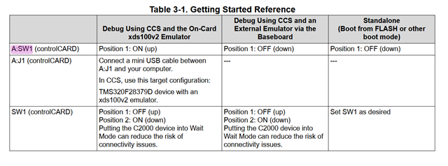
- on the card A;SW1 is on '10' position. Position 1 is ON and position 2 is off. This allows debugging using XDS100V2 onboard emulator.
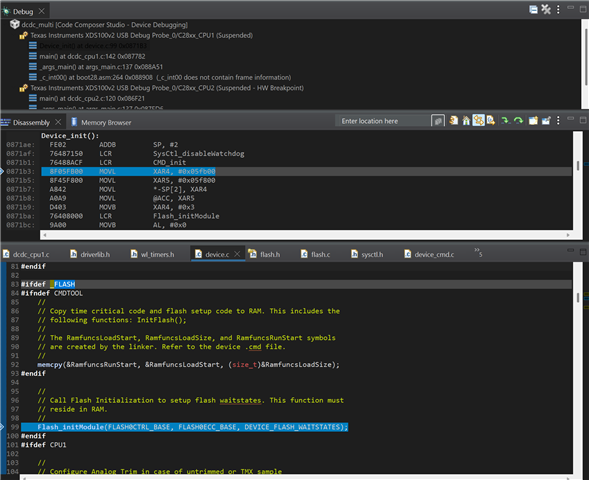
- Program is built with FLASH config as Active.
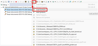
- Program is loaded either as 'Debug as -> 1 code composer debug session' or 'Run -> Load -> Project name'.
- When 'Debug as ...' option is used I could see both cpus halted at main symbol which could be resumed and will work fine.The CPUs will continue running even when Debug session is terminated
- When 'Run' option is used, I could briefly see that CCS switches to Debug perspective and then exits. CPUs don't start.
- I turn off the power (from the based board).
- Disconnect the usb cable from the control card. Used for programming/debugging with XDS100V2.
- All the permutations of the following are tried:
- A;SW1 position 1 is turned OFF. This is to put NTRST = 0
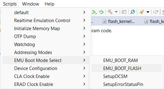
- SW1 both positions or turned ON. This is to put the boot config in 'GetMode'.
- in practice I have tried all the possible combination of positions of the switches, just to make sure I'm not mistaken on which side is on or off.
- Turn the power on
I expect the terminals to show that CPUs reset and start the program.
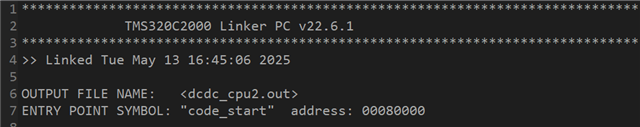
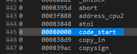
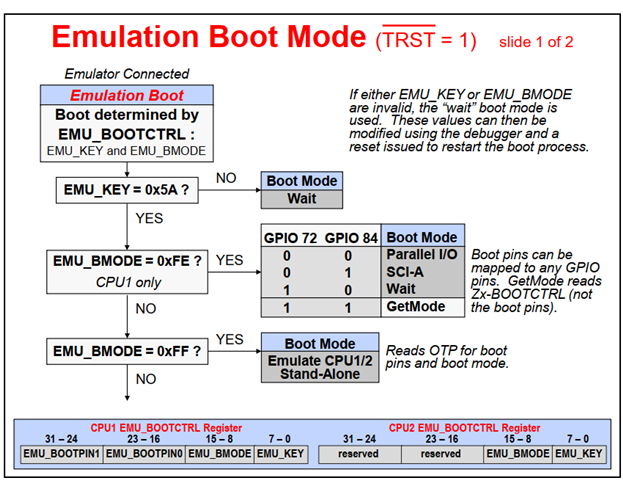
In a debug session, from looking at the registers, I've confirmed that the Zx-BOOTCTRL values don't have 0x5A in them.
What am I missing?
The project is based on a TI example, so all the configs are identical to "sci_ex2_sysconfig".
I'm running CCS 12.8.1.00005 on Windows 11 Professional. I'm Using 'C200Ware_5_04_00_00' and 'ti-cgt-C2000_22.6.1.LTS'.
Thanks in advance.