This thread has been locked.

If you have a related question, please click the "Ask a related question" button in the top right corner. The newly created question will be automatically linked to this question.

TMS320F28P650DK: MCan and Message RAM

Part Number: TMS320F28P650DK

Tool/software:

Dear TI support team,

I’m working with M-Can peripheral belonging to TMS320F28P650DK9, and I have a question related to the memory allocation of Standard Message ID Filter and Extended Message ID Filter.

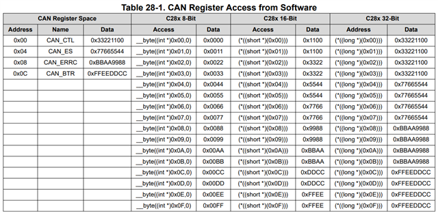
Document SPRUIZ1B states RAM memory allocation is 32-bit word addresses and according to figures

Figure 35-23, Standard Message ID Filter Element Structure is 32 bits wide

Figure 35-24, Extended Message ID Filter Element Structure is 64 bits wide.

 Now I'm going to describe my example.

For the standard filter, my setting is

    st_stdFiltElem_0.sfid2  = 0x3FF;                      

    st_stdFiltElem_0.sfid1  = 0x000;                      

    st_stdFiltElem_0.sfec   = 0x5;   

    st_stdFiltElem_0.sft    = 0x0;


and for the extended filter, the setting is

    st_extFiltElem_0.efid2  = 0x11223344;

    st_extFiltElem_0.efid1  = 0x55667788;

    st_extFiltElem_0.efec   = 0x1;

    st_extFiltElem_0.eft    = 0x1;


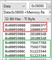
If I look the RAM memory from 0x5 9000 address, I see that

  • Two 32 bit words are allocated for the standard filter: refer to the red square
  • Four 32bit-words are allocated for the extended filter: refer to the green square

The following drivelib functions fill the RAM memory area


MCAN_addStdMsgIDFilter(MCANA_DRIVER_BASE, 0U, &st_stdFiltElem_0);

MCAN_addExtMsgIDFilter(MCANA_DRIVER_BASE, 0U, &st_extFiltElem_0);


So, my question is: according to the RAM memory view, it looks that there is memory consumption, or too much memory usage.

Is it correct?

If yes, why?

Best regards,

Ettore

  • Hi Ettore,

    CAN (DCAN and MCAN) is a byte-addressable peripheral, since they both were originally designed to interface to ARM cores. However, the c28x CPU is natively a 16-bit processor, meaning each address generated by the 28x CPU points to a location storing 16 bits. For example, every address in Flash or RAM stores 16 bits. To interface a byte addressable module to a 16-bit CPU, a byte addressing bridge was designed. What you see is caused by the byte addressing bridge.

    This is explained further in 28.2.2 Address/Data Bus Bridge in page 2817 of www.ti.com/lit/SPRUIW9. This explanation is also applied to MCAN message RAM.

    28.2.2 Address/Data Bus Bridge

    The CAN module uses a special addressing scheme to support byte accesses. It is recommended to only use 32-bit accesses to the CAN registers using the HWREG_BP() macro that uses the __byte_peripheral_32() intrinsic. If 16-bit accesses are to be used, the lower 16-bits must be written to the register's address, and the upper 16-bits must be written to the register's address plus 2. Because of the bus bridge, the view of the CAN module's register space through the Code Composer StudioTm (CCS) IDE memory window does not always match the actual addressing. When the view mode is 32-bit or 16-bit, even addresses are effectively duplicated; odd addresses can be ignored. When the view mode is 8-bit, even addresses from within the CAN module are duplicated into the odd addresses in the CCS memory view; odd addresses from the module are not displayed.