This thread has been locked.

If you have a related question, please click the "Ask a related question" button in the top right corner. The newly created question will be automatically linked to this question.

TMS320F2800156-Q1: How to merge Bitfield code & Driver-lib code in one CCS project?

Part Number: TMS320F2800156-Q1

Tool/software:

Hi Team,

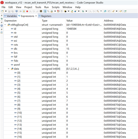
 I am currently working on the F2800156-Q1 (32-pin) microcontroller for a PMSM controller project. We have developed the code for Motor controller logic using the bitfield format but the MCAN communication code part is done in driver-lib format since there are no bitfield examples on MCAN at this point. Please assist me how merge  Bitfield code & Driver-lib code in one CCS project?

Regards

Shivani

  • Hi Shivani,

    It should be possible to combine device files in both driverlib and bit-field in your example please check out this forum post for more information. The key thing is to make sure that you've properly included the device_support files in your project.

    https://e2e.ti.com/support/microcontrollers/c2000-microcontrollers-group/c2000/f/c2000-microcontrollers-forum/889632/ccs-tms320f28075-tms320f28075-driverlib-and-bit-fields 

    You can also check out this software guide. It also has a link to the bit-field and driverlib app note.

    https://software-dl.ti.com/C2000/docs/software_guide/c2000ware/drivers.html

    Regards,

    Ozino

  • Hi Ozino,

    Sorry For late response, 

    I have gone through the both link you provided, I have managed to setup both driver lib and Bitfield in single project successfully, When I tried to Transmit a CAN message, the build  and debug are running successfully but no CAN message receive on the PCAN tool & Vice-versa. The code get struck in the loop, but when I run the same code in driver-lib project file, it works fine. I did not understand why this happen?

    Regards 

    Shivani

  • Hi Shivani,

    Is your CAN setup calling any bit-field code? What part of the loop is your code stuck in? Is it in the CAN setup routine? Please ensure that the device setup is  only being run once now that you've got both versions of the software supported.

    Regards,

    Ozino

  • Hi Ozino,

    1. My MCAN setup is not calling any bit-field code.

    2. I did not use any interrupt/ISR.

    I am sharing the code file with you for review. The implementation does not use any interrupts; instead, it operates within a while loop to verify the loop execution time. I have created two separate projects: one that includes only DriverLib files, and another that incorporates both DriverLib and bitfield files. I ran the same code in both projects. However, I observed that only the DriverLib-based project produces output on the CANH and CANL lines, the normal bit rate is 500kb/s & data bit rate is 2Mb/s

    Loop execution time - using GPIO29

    No output is received  when code is debuged in combined DriverLib and bitfield project file (PCAN Tool setting is same).  In this code I have not added any bitfield part till now, but i want to add in future.

    One more important thing to mentioned  in combined DriverLib and bitfield project file i have tested GPIO toggling and EPWM generation, both are working fine but i am facing the problem with MCAN only.

    Problem I faced - 1. Whenever I started transfering data from PCAN tool to MCU, PCAN LED started blinking red, no data transfer is done. 

    2.  Whenever I started transfering data from MCU to PCAN tool, no output waveform is seen at CANH & CANL pin, no data received at PCAN tool. (TBPRP =1)

    Does combined DriverLib and bitfield project file affect loop execution process?

    I did not understand why this is happening because the same code runs fine in only DriverLib file project


    // Include Files
    #include "driverlib.h"
    #include "device.h"
    #include "inc/stw_types.h"
    #include "inc/stw_dataTypes.h"
    #include <string.h>
    
    // Defines
    #define NUM_OF_MSG                      (1U)
    #define MCAN_STD_ID_FILTER_NUM          (1U)
    #define MCAN_EXT_ID_FILTER_NUM          (0U)
    #define MCAN_FIFO_0_NUM                 (0U)
    #define MCAN_FIFO_0_ELEM_SIZE           (MCAN_ELEM_SIZE_64BYTES)
    #define MCAN_FIFO_1_NUM                 (0U)
    #define MCAN_FIFO_1_ELEM_SIZE           (MCAN_ELEM_SIZE_64BYTES)
    #define MCAN_RX_BUFF_NUM                (10U)
    #define MCAN_RX_BUFF_ELEM_SIZE          (MCAN_ELEM_SIZE_64BYTES)
    #define MCAN_TX_BUFF_SIZE               (0U)
    #define MCAN_TX_FQ_SIZE                 (0U)
    #define MCAN_TX_BUFF_ELEM_SIZE          (MCAN_ELEM_SIZE_64BYTES)
    #define MCAN_TX_EVENT_SIZE              (0U)
    
    //  Defining Starting Addresses for Message RAM Sections,
    //  (Calculated from Macros based on User defined configuration above)
    #define MCAN_STD_ID_FILT_START_ADDR     (0x0U)
    #define MCAN_EXT_ID_FILT_START_ADDR     (MCAN_STD_ID_FILT_START_ADDR + ((MCAN_STD_ID_FILTER_NUM * MCANSS_STD_ID_FILTER_SIZE_WORDS * 4U)))
    #define MCAN_FIFO_0_START_ADDR          (MCAN_EXT_ID_FILT_START_ADDR + ((MCAN_EXT_ID_FILTER_NUM * MCANSS_EXT_ID_FILTER_SIZE_WORDS * 4U)))
    #define MCAN_FIFO_1_START_ADDR          (MCAN_FIFO_0_START_ADDR + (MCAN_getMsgObjSize(MCAN_FIFO_0_ELEM_SIZE) * 4U * MCAN_FIFO_0_NUM))
    #define MCAN_RX_BUFF_START_ADDR         (MCAN_FIFO_1_START_ADDR + (MCAN_getMsgObjSize(MCAN_FIFO_1_ELEM_SIZE) * 4U * MCAN_FIFO_1_NUM))
    #define MCAN_TX_BUFF_START_ADDR         (MCAN_RX_BUFF_START_ADDR + (MCAN_getMsgObjSize(MCAN_RX_BUFF_ELEM_SIZE) * 4U * MCAN_RX_BUFF_NUM))
    #define MCAN_TX_EVENT_START_ADDR        (MCAN_TX_BUFF_START_ADDR + (MCAN_getMsgObjSize(MCAN_TX_BUFF_ELEM_SIZE) * 4U * (MCAN_TX_BUFF_SIZE + MCAN_TX_FQ_SIZE)))
    
    // Global Variables.
    int32_t     error = 0;
    MCAN_RxBufElement rxMsg[NUM_OF_MSG], rxMsg1;
    int32_t loopCnt = 0U;
    MCAN_RxNewDataStatus newData;
    
    // Function Prototype
    static void MCANConfig(void);
    
    void main()
    {
        int i = 0;
        volatile uint32_t mode = 0U;
        uint32_t dataBytes = 64;
    
        // Initialize device clock and peripherals
        Device_init();
    
        // Initialize GPIO and unlock the GPIO configuration registers
        Device_initGPIO();
    
        // Configure the divisor for the MCAN bit-clock
        SysCtl_setMCANClk(SYSCTL_MCANCLK_DIV_3);
    
        // Configure GPIO pins for MCANTX/MCANRX operation
        GPIO_setPinConfig(DEVICE_GPIO_CFG_MCANRXA);
        GPIO_setPinConfig(DEVICE_GPIO_CFG_MCANTXA);
    
        GPIO_setPadConfig(29, GPIO_PIN_TYPE_PULLUP);    // Enable pullup on GPIO29
        GPIO_writePin(29, 1);                           // Load output latch
        GPIO_setPinConfig(GPIO_29_GPIO29);              // GPIO29 = GPIO29
        GPIO_setDirectionMode(29, GPIO_DIR_MODE_OUT);   // GPIO29 = output
    
        // Initialize message to receive
        rxMsg[loopCnt].id = 0U;
        rxMsg[loopCnt].rtr = 0U;
        rxMsg[loopCnt].xtd = 0U;
        rxMsg[loopCnt].esi = 0U;
        rxMsg[loopCnt].rxts = 0U;   // Rx Timestamp
        rxMsg[loopCnt].dlc = 0U;
        rxMsg[loopCnt].brs = 0U;
        rxMsg[loopCnt].fdf = 0U;
        rxMsg[loopCnt].fidx = 0U;   // Filter Index
                                    // (of matching Rx acceptance filter element)
        rxMsg[loopCnt].anmf = 0U;   // Accepted Non-matching Frame
    
        for(i = 0; i < dataBytes; i++)  // Initialize receive buffer to 0
        {
            rxMsg[loopCnt].data[i]  = 0;
        }
    
        // Configure the MCAN Module.
        MCANConfig();
    
        while(1)
    {
        GPIO_writePin(29, 1);
        // Get the New Data Status.
        MCAN_getNewDataStatus(MCANA_DRIVER_BASE, &newData);
    
        if((newData.statusLow & (1UL << 0U)) != 0)
        {
            MCAN_readMsgRam(MCANA_DRIVER_BASE, MCAN_MEM_TYPE_BUF, loopCnt, 0, &rxMsg[loopCnt]);
        }
        else
        {
            error++;
            //  Interrupt handling for other interrupt sources goes here
        }
    
        //  Clearing the NewData registers
        MCAN_clearNewDataStatus(MCANA_DRIVER_BASE, &newData);
    
        GPIO_writePin(29, 0);
    }
    
        // Stop Application.
       asm("   ESTOP0");
    }
    
    static void MCANConfig(void)
    {
        MCAN_InitParams initParams;
        MCAN_MsgRAMConfigParams    msgRAMConfigParams;
        MCAN_StdMsgIDFilterElement stdFiltelem;
        MCAN_BitTimingParams       bitTimes;
    
        //  Initializing all structs to zero to prevent stray values
        memset(&initParams, 0, sizeof(initParams));
        memset(&msgRAMConfigParams, 0, sizeof(msgRAMConfigParams));
        memset(&stdFiltelem, 0, sizeof(stdFiltelem));
        memset(&bitTimes, 0, sizeof(bitTimes));
    
        // Configure MCAN initialization parameters
        initParams.fdMode            = 0x1U; // FD operation enabled.
        initParams.brsEnable         = 0x1U; // Bit rate switching enabled
    
        // Initialize Message RAM Sections Configuration Parameters
        msgRAMConfigParams.flssa                = MCAN_STD_ID_FILT_START_ADDR;
        // Standard ID Filter List Start Address.
        msgRAMConfigParams.lss                  = MCAN_STD_ID_FILTER_NUM;
        // List Size: Standard ID.
        msgRAMConfigParams.rxBufStartAddr       = MCAN_RX_BUFF_START_ADDR;
        // Rx Buffer Start Address.
        msgRAMConfigParams.rxBufElemSize        = MCAN_RX_BUFF_ELEM_SIZE;
        // Rx Buffer Element Size.
    
        // Initialize Rx Buffer Configuration parameters.
        stdFiltelem.sfid2              = 0x0U; // Standard Filter ID 2.
        // Configuring received frame to be stored in buffer element 0
        stdFiltelem.sfid1              = 0x4U; // Standard Filter ID 1.
        // Confifuring frames with msg ID = 0x4U to be accepted by filter element
        stdFiltelem.sfec               = 0x7U; // Store into Rx Buffer
                                               // configuration of SFT[1:0] ignored
    
        // Initialize bit timings.
        bitTimes.nomRatePrescalar   = 0x3U; // Nominal Baud Rate Pre-scaler
        bitTimes.nomTimeSeg1        = 0xEU; // Nominal Time segment before SP
        bitTimes.nomTimeSeg2        = 0x3U; // Nominal Time segment after SP
        bitTimes.nomSynchJumpWidth  = 0x4U; // Nominal SJW
        bitTimes.dataRatePrescalar  = 0x0U; // Data Baud Rate Pre-scaler
        bitTimes.dataTimeSeg1       = 0xEU; // Data Time segment before SP
        bitTimes.dataTimeSeg2       = 0x3U; // Data Time segment after SP
        bitTimes.dataSynchJumpWidth = 0x4U; // Data SJW
    
        // Wait for memory initialization to happen.
        while(FALSE == MCAN_isMemInitDone(MCANA_DRIVER_BASE))
        {
        }
    
        // Put MCAN in SW initialization mode.
        MCAN_setOpMode(MCANA_DRIVER_BASE, MCAN_OPERATION_MODE_SW_INIT);
    
        // Wait till MCAN is not initialized.
        while (MCAN_OPERATION_MODE_SW_INIT != MCAN_getOpMode(MCANA_DRIVER_BASE))
        {
    
        }
    
        // Initialize MCAN module.
        MCAN_init(MCANA_DRIVER_BASE, &initParams);
    
        // Configure Bit timings.
        MCAN_setBitTime(MCANA_DRIVER_BASE, &bitTimes);
    
        // Configure Message RAM Sections
        MCAN_msgRAMConfig(MCANA_DRIVER_BASE, &msgRAMConfigParams);
    
        // Configure Standard ID filter element
        MCAN_addStdMsgIDFilter(MCANA_DRIVER_BASE, 0U, &stdFiltelem);
    
        // Take MCAN out of the SW initialization mode
        MCAN_setOpMode(MCANA_DRIVER_BASE, MCAN_OPERATION_MODE_NORMAL);
    
        while (MCAN_OPERATION_MODE_NORMAL != MCAN_getOpMode(MCANA_DRIVER_BASE))
        {
    
        }
    }

  • Thanks for the information.

    I'm going to forward this post to the MCAN experts. In the meantime, can you confirm that your main() functions device startup routine is initialized correctly using only driverlib code?

  • Hi Shivani,

    It should be straightforward.  In the c file where MCAN driverlib functrions are being called add the header file:

       #include "driverlib.h"

    Also in the CCS project Include Options, be sure to add these paths:

       [path where C2000 root resides]\device_support\f280015x\common\include

       [path where C2000 root resides]\driverlib\f280015x\driverlib

    In your CCS project add the following files from  [path where C2000 root resides]\driverlib\f280015x\driverlib:

       - mcan.c

       - interrupt.c (if you are using the interrupt functions for driverlib)

    You may need to add other driverlib c files.  For instance, if after compiling and you are getting an error/link warning for a function call that starts with Sysctl_* then file sysctl.c needs to be added to the CCS project. It is pretty intuitive on what driverlib.c file needs to be added depending on the function name that causes a compile or linking error.

    I suggest you start first to run and play with any MCAN driverlib examples as you can use this as a guide/reference when mergind driverlib function calls with bitfield routines.

    Regards,

    Joseph 

  • Hi Joseph

    thank you for your assistance. 

    I am trying it, just provide some time. 

    Regards, 

    Shivani

  • Hi Ozino,

    thank you  for your assistance. 

     Yes, main() functions device startup routine is initialized correctly using only driverlib code. 

    I am trying it, just provide some time.

    Regards, 

    Shivani

  • Hi Shivani,

    Ok, let me know if you have issues merging the MCAN driverlib codes and from your response below, seems that you are using driverlib functions already for device initialization.  You may not need to add the mcan.c file in your project then.  Probably just calling the driverlib MCAN functions would work as driverlib dependencies are already in your main().

    Regards,

    Joseph 

  • Thank you Joseph, 

    Bit-field & Driver lib Merging issue is resolved. I am getting the output.

    Regards

    Shivani

  • Hi Shivani,

    Glad to know you were successful with the bitfield and driverlib merge with your F280015x project.

    Regards,

    Joseph