This thread has been locked.

If you have a related question, please click the "Ask a related question" button in the top right corner. The newly created question will be automatically linked to this question.

TMS320F28P650DK: Problems with word shift in slave DMA SPI transmission

Part Number: TMS320F28P650DK
Other Parts Discussed in Thread: SYSCONFIG, C2000WARE

Tool/software:

I am using the TMS320F28P650DK device as an SPI peripheral (slave) to send and receive data to/from another (controller) micro in my system. The other micro generates clock and chip select signals.

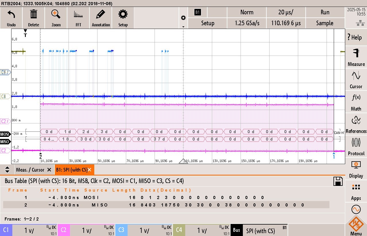
I am trying to send quite a bit of data so am setting things up so we have DMA manage data flow into and out of the SPI peripherals. As a starting point I want to send/receive 16x 16 bit words so set the C2000 slave to use data in 16 bit words with DMA. The other micro generates the correct chip select and clock lines to support this. The figure below shows an example transmission with the clock (C2, purple) cycling 256 times for the 16x 16 bit words.

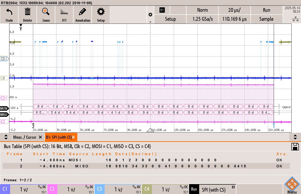
The data transmission works but the position of the data in the DMA transfer from the C2000 (MISO) looks like it has wrapped around by one word. The struct I setup for the data transmission from the C2000 part is:-

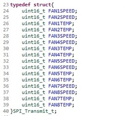
The first 16 bit word word on the MISO transmission is the FAN2SPEED data (I checked this in practice by changing that data and seeing just the first word bits change). The second word is FAN1TEMP and the third word is FAN2TEMP. The FAN1SPEED which should have been the first word of the transmission is the 16th word, right at the end of the transmission. It looks like it has wrapped around.

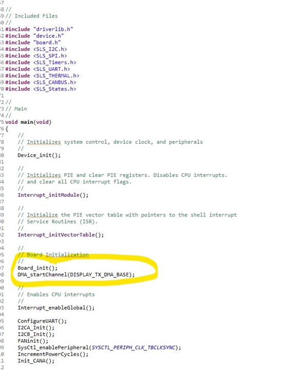
My question is what would cause this behaviour? I get a feeling it might be how the FIFO is set up or maybe the FIFO isn't empty before the transmission starts. Both DMA channels are running continuously, enabled in sysconfig. Maybe I should be starting them and stopping them based on activity on the incoming nCS or clock lines from the SPI controller?

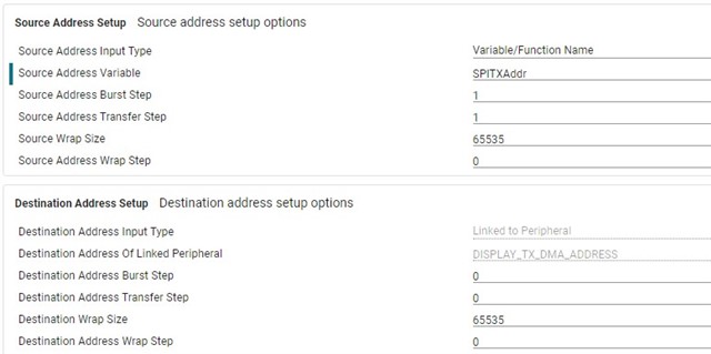
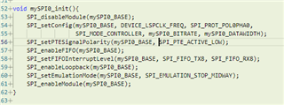
Here is the SPIC peripheral setup in sysconfig:-

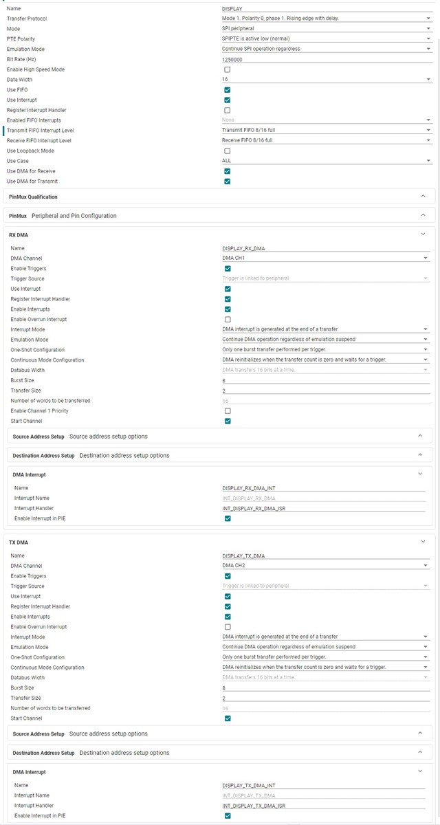
Any ideas are most welcome.

Thanks, Iain

  • Hi Iain,

    The most important setting for SPI/DMA operation is to have a matching SPI FIFO level and DMA burst size, which it looks like you do have correctly configured here (FIFO level = DMA burst size = 8.) Note that with these configurations the SPI should only trigger the DMA to move a burst of data over if there are at least 8 spots in the TX FIFO available, so there should be no overwrite of data in the TX FIFO happening. Even with continuous mode enabled, the DMA still needs to receive triggers from the SPI to actually do anything, so I don't see this as being your issue either.

    Can you show what configurations you are using for the source and destination addresses of the TX DMA channel? I suspect the DMA could just be starting at the wrong spot in memory. 

    Also, have you already tried running the spi_ex5_loopback_dma C2000ware example unchanged to verify your hardware setup? 

    Best Regards,

    Delaney

  • Hi Delaney,

    Thanks for getting back to me. The source and destination addresses for the TX DMA channel are:-

    I think this is correct but this is also the first time I used DMA for SPI data transfer so I could be misunderstanding something. The source address for my transmission is SPITXAddr and the address increments by one word for each transmission in the burst. 

    The transmission packet I see in the MISO (POCI in new terminology!) is stable in that the data is not changing position over time(i.e. the data words I do see are locked into their place in the packet, just with an offset of one word)

    I'll take a look at the example code too and see if the behaviour is different.

    Many Thanks,

    Iain

  • Hi Delaney,

    Based on your message above, I tried changing the address definition of where the DMA transmit buffer points to. Originally I had:-

    const void *SPITXAddr = (const void *)&SPI_TX;   // Point DMA Address Transmit Buffer to Transmit Data Buffer

    I experimented with changing this to:-

    const void *SPITXAddr = ((const void *)&SPI_TX)-1;   // Point DMA Address Transmit Buffer to Transmit Data Buffer

    I expect this is very bad practice and unreliable but it did impact the POCI transmission data in the way I was hoping it would:-

    You can see that the MISO transmit packet now starts with the correct data and the first four words are FAN1SPEED, FAN2SPEED, FAN1TEMP and FAN2TEMP. This isn't a fix but it might help us to understand what is going on. Interestingly when I do this, if I try to write data into the last word of my struct (FAN8TEMP), it doesn't appear in my MISO transmission, i.e. the last 16 bit word of MISO can no longer be written via the DMA)

    Does this prompt any thoughts about what might be wrong?

    Thanks, 

    Iain

  • Hi Delaney, 

    OK, I think I have fixed this problem now and wanted to share what I found. I firstly return the address definition back to the original:-

    const void *SPITXAddr = (const void *)&SPI_TX;   // Point DMA Address Transmit Buffer to Transmit Data Buffer

    I read on some of the other posts that the timing of when the DMA channels are enabled can make a difference. With my original code, I selected to enable both the RX and TX channels from within the sysconfig tool which I guess enables the peripherals early on. I experimented with changing the TX DMA channel to initially be off within sysconfig and then enable it just before interrupts are enabled in my startup code:-

    This change results in the words in the DMA transmit on POCI to be in the correct places and I can write correctly to all sixteen word positions now. My only issue now is I would like to understand why this fixed the problem as I'm not sure I understand this 100%. BTW - the other micro could be exercising the SPI bus as the C2000 boots so maybe it is a timing/interrupt issue?

    Any idea?!

    Thanks for your help,

    Iain

  • Hi Iain,

    Your original addressing line should be good; it matches the code in the software example: const void *destAddr = (const void *)rData;

    I see, yes if you start the DMA channels inside Sysconfig, then any triggers that come in after the DMA_startChannel() line in the Sysconfig generated code will start a burst on the DMA channels since they will be enabled. Sysconfig will put all the DMA initializations before the SPI initializations in the generated code, see below screenshot.

    Since the SPI is being used as the trigger source for both of your DMA channels, I believe one of the lines in the SPI initializations is triggering the DMA before the SPI is actually able to transmit anything (since the last line of code is enabling the SPI module). This is basically like writing to the SPI TX buffer register when the module isn't enabled, it will do nothing. 

    The difference you see with the new code is that the DMA channel is enabled after all SPI initializations are done, so it is actually able to transmit the data transferred to the SPI register by the DMA. This way the DMA channels cannot transfer data until the SPI module is fully initialized. 

    Please upvote this response if it answers your question. Slight smile

    Best Regards,

    Delaney