This thread has been locked.

If you have a related question, please click the "Ask a related question" button in the top right corner. The newly created question will be automatically linked to this question.

TMS320F28P650DK: When implementing Endat communication using CLB, it was found that SPI TX could not be sent normally

Part Number: TMS320F28P650DK

Tool/software:

Hello engineers,

SPICLK and PTE are normal. Data was written to SPITXFIFO and three pieces of data were written. It was observed that the data had entered the SPIDAT shift register, but it just couldn't be sent out.


LSPCLK is configured to 20 MHz.SPI is configured as a slave device. The specific configuration is as follows:

void endat22_spi_fifo_init() {

    //
    // Initialize SPI FIFO registers
    //
    SPI_disableModule(PM_ENDAT22_SPI);
    SPI_disableLoopback(PM_ENDAT22_SPI);
    SPI_setConfig(PM_ENDAT22_SPI, DEVICE_LSPCLK_FREQ_20M, SPI_PROT_POL1PHA0,
                  SPI_MODE_PERIPHERAL, 500000, 9);
    SPI_enableFIFO(PM_ENDAT22_SPI);
    SPI_setEmulationMode(PM_ENDAT22_SPI, SPI_EMULATION_FREE_RUN);
    SPI_enableModule(PM_ENDAT22_SPI);
    SPI_resetTxFIFO(PM_ENDAT22_SPI);
    SPI_resetRxFIFO(PM_ENDAT22_SPI);

}


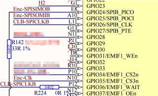
CLB generates SPICLK(200kHz) and connects it to the GPIO port of SPICLK through an external connection,GPIO_23 has been grounded:

    GPIO_setPinConfig(GPIO_24_SPIB_PICO);
    GPIO_setPadConfig(24, GPIO_PIN_TYPE_STD | GPIO_PIN_TYPE_PULLUP);
    GPIO_setQualificationMode(24, GPIO_QUAL_ASYNC);

    GPIO_setPinConfig(GPIO_25_SPIB_POCI);
    GPIO_setPadConfig(25, GPIO_PIN_TYPE_STD);
    GPIO_setQualificationMode(25, GPIO_QUAL_ASYNC);

    //原理图中GPIO27应为SPIB_PTE,但未接地;临时使用GPIO23替代
    GPIO_setPinConfig(GPIO_23_SPIB_PTE);
    GPIO_setPadConfig(23, GPIO_PIN_TYPE_STD);
    GPIO_setQualificationMode(23, GPIO_QUAL_ASYNC);

    GPIO_setPinConfig(GPIO_26_SPIB_CLK);
    GPIO_setPadConfig(26, GPIO_PIN_TYPE_STD | GPIO_PIN_TYPE_PULLUP);
    GPIO_setQualificationMode(26, GPIO_QUAL_ASYNC);


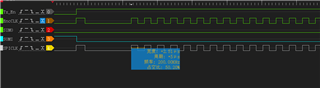
The SPICLK generated by the measured CLB is shown in Figure 4 below:

  • Hi Lin,

    Does the code work as expected without CLB input as SPICLK?

    Can you verify that the CLB CLK is properly replacing the SPICLK? Does higher CLB based CLK values work since 200 khz is relatively slow? SPI needs to follow all of these timing requirements to operate accordingly. Based on below code, I cannot confirm, since it looks like the regular SPICLK is being used?

        GPIO_setPinConfig(GPIO_24_SPIB_PICO);
        GPIO_setPadConfig(24, GPIO_PIN_TYPE_STD | GPIO_PIN_TYPE_PULLUP);
        GPIO_setQualificationMode(24, GPIO_QUAL_ASYNC);

        GPIO_setPinConfig(GPIO_25_SPIB_POCI);
        GPIO_setPadConfig(25, GPIO_PIN_TYPE_STD);
        GPIO_setQualificationMode(25, GPIO_QUAL_ASYNC);

        //原理图中GPIO27应为SPIB_PTE,但未接地;临时使用GPIO23替代
        GPIO_setPinConfig(GPIO_23_SPIB_PTE);
        GPIO_setPadConfig(23, GPIO_PIN_TYPE_STD);
        GPIO_setQualificationMode(23, GPIO_QUAL_ASYNC);

        GPIO_setPinConfig(GPIO_26_SPIB_CLK);
        GPIO_setPadConfig(26, GPIO_PIN_TYPE_STD | GPIO_PIN_TYPE_PULLUP);
        GPIO_setQualificationMode(26, GPIO_QUAL_ASYNC);

    Why is the PICO and CLK being pulled up? SPI pins do not require pull-up/down resistor for operation. 

    In addition, if you are sending less than 16-bits at a time, is the data bit-shifted accordingly?

    Best Regards,

    Aishwarya

  • Hi Aishwarya,

    I followed your suggestions for troubleshooting and removed the pull - up. However, I still couldn't identify the problem. The GPIO26 SPICLK was confirmed to have changes through debug mode (but the frequency is uncertain). Finally, I came up with the idea of modifying the CLB's SPICLK output to be directly internally connected to SPICLK instead of an external GPIO connection. After the modification, it was able to send data normally. Thank you sincerely for your help and the ideas you provided.

    Best Regards,

    Lin Haonan