This thread has been locked.

If you have a related question, please click the "Ask a related question" button in the top right corner. The newly created question will be automatically linked to this question.

TMS320F28035: ePWM, Servo Motor Buzzing/Stuttering

Part Number: TMS320F28035

Tool/software:

Hello,

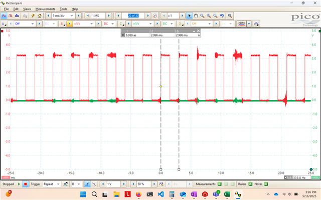
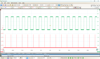
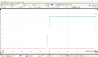
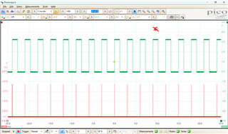
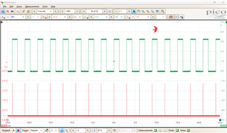
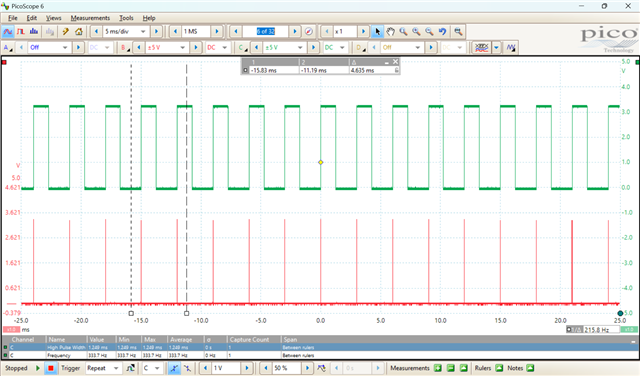
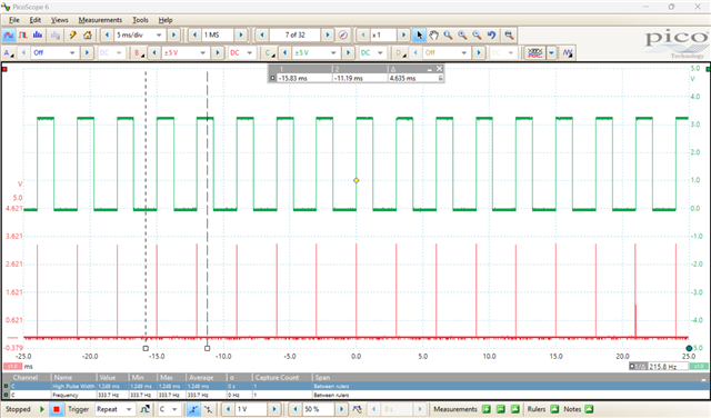
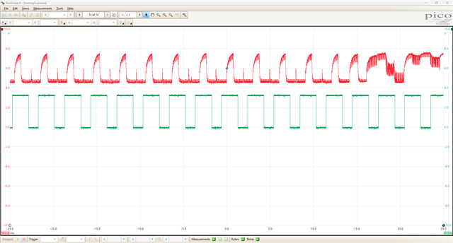
I am utilizing a 56 pin F28035 with ePWM to move a servo motor. Randomly, the servo motor will start buzzing/stuttering at certain points in its traversal. I am posting the code and a video to show what is happening. I have tried utilizing different frequencies between 50Hz to 333Hz, but the same behavior arises. For reference, the servo utilizes 333Hz. Are there any settings I should look to change or any register behavior I should look for? Normally, we use the 80 pin variant of the F28035, and buzzing does not happen as often. Thank you.

//
// Included Files
//
#include "DSP28x_Project.h"     // Device Headerfile and Examples Include File

Uint16 isrCntr = 0;
Uint16 pos = 0;
Uint16 dir = 0;

__interrupt void pwm2Isr(void);

//
// Main
//
void main(void)
{
    //
    // Step 1. Initialize System Control:
    // PLL, WatchDog, enable Peripheral Clocks
    // This example function is found in the DSP2803x_SysCtrl.c file.
    //
    InitSysCtrl();

    InitPieCtrl();

    IER = 0x0000;
    IFR = 0x0000;

    InitPieVectTable();

    InitEPwm2Gpio();

    EALLOW;
    GpioCtrlRegs.GPAMUX2.bit.GPIO23 = 0;
    GpioCtrlRegs.GPADIR.bit.GPIO23 = 1;
    GpioDataRegs.GPACLEAR.bit.GPIO23 = 1;
    EDIS;

    EALLOW;
    SysCtrlRegs.PCLKCR0.bit.TBCLKSYNC = 0;
    EDIS;
    
    //
    // Setup TBCLK
    //
    EPwm2Regs.TBSTS.all = 0;
    EPwm2Regs.TBPHS.half.TBPHS = 0;
    EPwm2Regs.TBCTR = 0;
    EPwm2Regs.TBCTL.bit.CTRMODE = TB_COUNT_UP;  // Count up.
    EPwm2Regs.TBCTL.bit.PHSEN = TB_DISABLE;     // Disable phase loading.
    EPwm2Regs.TBPHS.half.TBPHS = 0x0000;        // Phase is 0.
    EPwm2Regs.TBCTR = 0x0000;                   // Clear counter.
    EPwm2Regs.TBCTL.bit.HSPCLKDIV = 0;          // Clock ratio to SYSCLKOUT.
    EPwm2Regs.TBCTL.bit.CLKDIV = 6;

    //
    // Setup shadow register load on ZERO
    //
    EPwm2Regs.CMPCTL.bit.SHDWAMODE = CC_SHADOW;
    EPwm2Regs.CMPCTL.bit.LOADAMODE = CC_CTR_ZERO;

    //
    // Set actions
    //
    EPwm2Regs.AQCTLA.bit.ZRO = AQ_SET;      // Set PWM2A on Zero
    EPwm2Regs.AQCTLA.bit.CAU = AQ_CLEAR;    // Clear PWM2A on event A, up count

    EPwm2Regs.ETSEL.bit.INTSEL = 2;
    EPwm2Regs.ETPS.all = 1;
    EPwm2Regs.TBCTL.bit.SYNCOSEL = 3;

    EALLOW;
    SysCtrlRegs.PCLKCR0.bit.TBCLKSYNC = 1;
    EDIS;

    EALLOW;
    PieVectTable.EPWM2_INT = &pwm2Isr;
    EDIS;

    IER |= M_INT3;

    EINT;
    ERTM;

    PieCtrlRegs.PIEIER3.bit.INTx2 = 1;

    GpioDataRegs.GPASET.bit.GPIO23 = 1;

    EPwm2Regs.ETCLR.bit.INT = 1;
    EPwm2Regs.ETSEL.bit.INTEN = 1;
    EPwm2Regs.TBPRD = 2815;
    EPwm2Regs.CMPA.half.CMPA = 1407;
    pos = 1407;

    while (1) {}
}

__interrupt void pwm2Isr(void)
{
    if (pos < 1642 && dir == 0)
    {
        EPwm2Regs.CMPA.half.CMPA = pos++;
    }
    else if (pos == 1642)
    {
        isrCntr++;

        if (isrCntr > 1000)
        {
            isrCntr = 0;
            dir = 1;
            EPwm2Regs.CMPA.half.CMPA = pos--;
        }
    }
    else if (pos > 1172 && dir == 1)
    {
        EPwm2Regs.CMPA.half.CMPA = pos--;
    }
    else if (pos == 1172)
    {
        isrCntr++;
        if (isrCntr > 1000)
        {
            dir = 0;
            isrCntr = 0;
        }
    }

    EPwm2Regs.ETCLR.bit.INT = 1;
    PieCtrlRegs.PIEACK.all = PIEACK_GROUP3;
}

  • Hi JZ,

    Unfortunately the video does not show up. Can you probe the PWM outputs and verify that the expected waveforms are being generated?

    Are all your clock settings for the PWM the same across the 80 pin variant and your current one?

    Are all the same ePWM registers being applied? You can export the register content using CCS connected via JTAG and diff between your current pin variant and the 80 pin.

    Best,

    Ryan Ma

  • Hello Ryan,

    The clock settings are the same between the 80 pin and 56 pin. Using a TBCLK of 937500Hz.

    The only difference between the two is that usually on the 80 pin variant, we use ePWM1A as the signal going to the servo. With the 56 pin, I have to use ePWM2A.  Other than different ePWM modules, the register settings are the same.

    Here is a capture showing noise on the pwm pin. Other than the noise, the pulse width and period look good to me.

    Is there any way I can send the video to you? Thanks Ryan for the help.

  • Hi JZ,

    Looks like your PWM is operating as it should be based on your output. Do you see any weird issues with the PWM outputs?

    Are you using a custom board or our TI's EVM when testing? Perhaps something different with your board layout?

    Best,

    Ryan Ma

  • When the code reaches the isrCntr portion, I have seen 1 or 2 periods that are slightly shorter than the others. I'll see if I can get a capture of that.

    I am utilizing both custom boards and an f28035 control card w/ dock in testing.

  • Hi JZ,

    When are you updating your PWM values? Is your ISR frequency shorter than the next load event for the PWM for new compare values?

    Best,

    Ryan Ma

  • Hello Ryan,

    I am updating cmpa in isr and tbprd stays the same value.

  • Hi JZ,

    Can you scope the frequency of the ISR in respect to the PWM updates? Sounds like CMPA values may not be reflected in time before the next load event occurs.

    Were you able to capture the point in which your PWM duty is smaller than expected?

    Best,

    Ryan Ma

  • Hello Ryan,

    These two first scope pics show a gpio getting set and cleared inside the isr. This isr is set to happen when tbctr = tbprd and when first event intcnt = 1.

    Zooming in:

    These next two scope pics, I feel like the 12th pulsewidth (red) has some variance.

  • Hi jz,

    It is not possible to see if the 12th pulse width is different than the other pulse widths.

    Can you zoom in and compare the 12th pulse width by measuring the duty in comparison to the other pulse widths?

    Best,

    Ryan Ma

  • My bad. I used your idea and found another pulse width that looked like it had variance. Using the freq and high pulse width measurements, the frequency and pulse width are the same.

  • Hi JZ,

    If they are the same, then the PWM seems to be functioning correctly. Apologize, I cannot add much as to why you're experiencing buzzing or stuttering.

    Ryan Ma

  • Thanks Ryan for the help. If I may ask, any idea of what I could look into from this capture? The red signal is the supply to the board that feeds the servo. The green is the pwm that controls the motor. Thanks.

  • Apologies for the delay in response. It looks like just before the 15ms mark, the system behavior changes unexpectedly. Is there a PWM deadband issue causing a shoot-through current spike, perhaps? This would explain why there's an off-cycle power draw spike.

    Regards,
    Jason Osborn

  • Hello Jason,

    No worries. Dead band functionality is not enabled currently. Thanks.

  • Ah- Deadband (or similar functionality in software) should be enabled to avoid a condition where both the upper and lower FETs are active at the same time. What are you implementing to avoid that condition without deadband?

    Regards,
    Jason Osborn

  • I have no functionality in code to avoid this condition. I will look into the deadband pwm example. Thanks Jason.