This thread has been locked.

If you have a related question, please click the "Ask a related question" button in the top right corner. The newly created question will be automatically linked to this question.

TMS320F28376S: MCU starts SWI even Pin is not toggled

Part Number: TMS320F28376S
Other Parts Discussed in Thread: TDC7200,

Tool/software:

Dear Community

Current Situation:

We are using the TMS320F28376S microcontroller and a TDC7200 Time-to-Digital-Converter. our application uses SYS/BIOS (6.83.0.18) as RTOS.

We have configured a Timer as a Hwi which posts a SWI to start a measurement by sending the cmd to the TDC7200. The Hwi only posts the SWI. Within the SWI we handle the logic, cleaning up, reading TOF values form previous measurement and start a new measurement. We start every 1.6ms a measurement. We set up a Timer which is called every 200us, but at every 8th slice we send the measurement cmd.

void TIMER1_SWI() { // Timer Swi
  Controller::handleTimerIsr();
}

void TIMER1INT_ISR(UArg) { // Timer Hwi
  Swi_post(TIMER1_swi);
}

Surely, we set up an external Interrupt which posts a SWI, which handles the logic. This means, initiating a SPI transfer to to read the Values to calculate TOF1 and TOF2. The TDC7200 has an Interrupt line which pulls high, when the measurement is started and pulls low, when the measurement is finished.

extern const Swi_Handle XINT3_swi;
void XINT3_ISR(void) // 0x000DF0 XINT3
{
  Swi_post(XINT3_swi); // post a SWI
}

void XINT3_SWI() { // TDC Swi
  Controller::handleXintIsr();
}

Here is the SYS/BIOS configuration which we set up the ISR's which come from the TDC7200. The XINT3_ISR is the only one which is called in the Interrupt Group 12.// XINT Configuration which is triggered too often

var hwi11Params = new Hwi.Params();
hwi11Params.enableAck = true;
hwi11Params.instance.name = "XINT3_HWI";
Program.global.XINT3_HWI = Hwi.create(120, "&XINT3_ISR", hwi11Params);

// The corresponding SWI which is posted in XINT3_ISR

var swi10Params = new Swi.Params();
swi10Params.instance.name = "XINT3_swi";
swi10Params.priority = 10;
Program.global.XINT3_swi = Swi.create("&XINT3_SWI", swi10Params);

The Problem:

We observate that the ISR is started, even the TDC7200 does not have a falling edge on the Interrupt line. This can be seen at the picture below. We setup the TDC7200 using a 64 averaging.

In the first picture, one can see an expected measurement where the TDC7200 Interrupt has a short pulse. Within these pulse, there are 64 cycles done and we receive valid data from the TDC7200. This works charming. However, at the "bad" measurement after four cycles our SWI gets called, even the HWI should not be triggered due to a missing falling edge on the TDC7200 interrupt line.

The picture below is zoomed from the previous one. It is visible, that after 4 cycles we get called into the SWI, even the TDC7200 Interrupt does not get to 0. We know, that we are in the SWI since the SPI transfer from the TOF values are only implemented within this SWI. The values are of course wrong (we calculated negative TOF values). Interestingly, we get this bad measurement after 4 cycles. it is not quite regulary, but 1 to 2% of the measurements are like this.

Call stack and register values:

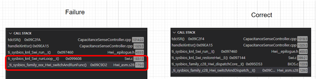
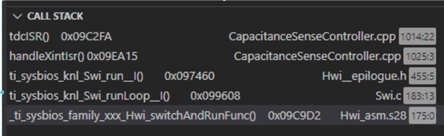
This is the callstack, when the measurement fails. 

The register values when SWI started are like following at a bad measurement:

PieCtrlRegs->PIEACK.ACK12 = 1

IFR->INT12 = 1

PIEIFR12->INTx1 = 1

Actions done:

As far as we know, SYS/BIOS should take care of the resetting the PIEIFR flag for the ISR as well as the acknowledge bit of the Interrupt group. I am not aware, what exactly the functions of SYS/BIOS do, but I have the feeling, that SYS/BIOS is not aware of this function call. This also explains the PIE registers which are not reset. However, most of the time, the measurement does work properly and the ISR's are called only when a falling edge is detected.

Also, the call stack is different to a good measurement. At a good measurement switchAndDispatch is called, which is more what I expected. As well, there is restoreHwi called, which I guess takes care of cleaning up the register values. It is not easy to understand SYS/BIOS because the available documentation is quite poor.
Have we missed configuring the SYS/BIOS properly? How can we be sure, that the Hwi is called, which posts the SWI?

How does the scheduler work, when we post a SWI in a HWI?

I really appreciate any hints for this problem.

Best regards, Robert

  • Hi Robert,

    I apologize for the delayed response. Are you still seeing the issue? I am looping in the SYS BIOS expert to comment on your questions.

    Best Regards,

    Delaney

  • Thank you. Yes we still have the issue.

  • Hi Robert,

    Are you able to put a GPIO toggle in XINT3_ISR() to see if it's getting triggered twice or if there's something else in the software that's inadvertently posting the Swi twice? You are correct that BIOS should be handling the ACK (I see you used hwi11Params.enableAck = true).

    From your diagram there doesn't seem to be a problem, but do you have some qualification enabled on the GPIO being used for XINT3?

    Whitney

  • Hi Whitney,

    yes, we see this in the second picture of my post. The yellow line is the chipselect which is only pulled low in the SWI which is posted by the HWI ISR from XINT3. The HWI from XINT3 is only called when the TDC7200 Interrupt line is pulled low (orange line). As you can see, this does not happen.

    I have not seen anything else in the Software which triggers the SWI. Furthermore, I could measure, that the XINT3_ISR is called, even it should not. As a consequence, SWI is called. The XINT3 is the onliest ISR in the group 12.

    I'm not quite sure, what you mean with qualification, but here is our TDC7200 setup.

    GPIO_SetupPinMux(c_TDC7200IntGpio, GPIO_MUX_CPU1, 0);
    GPIO_SetupPinOptions(c_TDC7200IntGpio, GPIO_INPUT, (GPIO_PULLUP | GPIO_SYNC));
    PieCtrlRegs.PIEIER12.bit.INTx1 = 1; // Enable PIE Group 12 XINT3
    IER |= M_INT12; // Enable CPU INT12

    GPIO_SetupXINT3Gpio(c_TDC7200IntGpio);

    XintRegs.XINT3CR.bit.POLARITY = 0; // Falling edge interrupt
    XintRegs.XINT3CR.bit.ENABLE = 1; // Enable XINT3

    // TDC chip select
    GPIO_SetupPinMux(s_spiChipSelect, GPIO_MUX_CPU1, 0);
    GPIO_SetupPinOptions(s_spiChipSelect, GPIO_OUTPUT, GPIO_PUSHPULL);
    GPIO_WritePin(s_spiChipSelect, s_gpioHighLevel);

    Thanks and best regards

    Robert

  • By qualification, I mean configuring an input with a small sampling window deal with noise. This can be configured as part of the GPIO_SetupPinOptions flags parameter (like using GPIO_QUAL6 instead of GPIO_SYNC).

    Whitney

  • ok, thanks.
    How would you rate our configuration?

  • You shouldn't write to  PieCtrlRegs.PIEIER12 directly. You should use SYS/BIOS functions to enable the interrupt.

    Like I mentioned previously, you could also try changing your XINT pin configuration to include some qualification:

    GPIO_SetupPinOptions(c_TDC7200IntGpio, GPIO_INPUT, (GPIO_PULLUP | GPIO_QUAL6));

    Otherwise, I don't see any issues with the code you've shared so far.

    Whitney

  • Hi Whitney,

    the GPIO_QUAL6 / GPIO_GPIO3 solved the problem. What I still do not understand why we get such a different call stack. This is the reason I have not looked at the GPIO settings and contributed my efforts to SYS/BIOS.
    This is the different call stack here:

    Have you got an answer to this?

    best regards

    Robert

  • In the scenario where everything works normally, I assume the sequence of context switches is likely something like

    Timer Hwi -> Timer Swi -> [some background task or something] -> XINT Hwi -> XINT Swi

    But if the XINT triggers very quickly before the Timer Swi completes, that context switch to XINT Swi could be happening from within the Timer Swi or at the end of it depending on their relative priorities. So I think the difference in the call stack is caused by whether the switch is happening coming out of the XINT Hwi or coming out of the other Swi. Would that make sense given the timing of events you're seeing?

    Whitney

  • Ok agreed.
    Your scenario is correct. However, I still do not understand why SYS/BIOS does not clear the acknowledge and flag bits of the corresponding isr line.
    As far as I understood, this should be handled by SYS/BIOS and independent of the calling function?

    Robert

  • If "enableAck" is true, the ACK gets cleared fairly early in the Hwi dispatcher (before your Hwi function gets called). You were seeing that it was set when you were halted at a breakpoint in the XINT Swi? I guess if there was an XINT event while you were sitting at the breakpoint, it might set the flag. Could that happen or would the TDC2700 hold that line high the whole time?

    Whitney