This thread has been locked.

If you have a related question, please click the "Ask a related question" button in the top right corner. The newly created question will be automatically linked to this question.

3-Phase current measurement with shunts

Other Parts Discussed in Thread: CONTROLSUITE, DRV8312

Hello,

I have to develop a sensorless FOC with PMSM / EC motor and F28335.

I found the application note sprc128 (PMSM3_2 3-Phase Sensorless Field Oriented Control) for the older F281x series but this should be also suitable for the Delfino.

On page 5 there's a schematic where is shown, that the current of two phases is measured with only two shunts between the lower switches and ground.

This kind of low cost current measurement is what I am highly interested in. Is there anywhere an application note which describes this method detailed?

Thank you in advance for helpful hints.

Kind regards,
Robert

  • Robert,

    In C2000's controlSUITE (http://www.ti.com/controlSUITE), you can download the hardware schematics, documentation, and software for a number of our kits.  I would recommend taking a look at the software and documentation for the TMDSHVMTRPFCKIT and maybe consider buying a kit (http://www.ti.com/f28xkits).  The projects inside that package use either the F28035 or the F28335 which should make things easier for you.

    In general, assuming the measurements of two legs is accurate enough, the third leg should be able to be recreated in software.


    Thank you,
    Brett

  • Robert,

    A couple of notes

     Using a 2-shunt technique is certainly feasible, and is usually what we show on most of our kits. But one of the things you should note going in is the limitations it places on you

    a. you will need to limit your duty cycle to something <100%, giving you a chance to measure both currents during the low-side on time.  What does limiting your duty cycle do?  It means you aren't able to apply full voltage to your system, so you aren't getting the maximum useful work out of your motor that is possible.  Are you really saving costs by removing one shunt if you have to use a slightly larger motor that is slightly less efficient in its use?

    b. you will need to have very fast opamps with fast settling time when these windows of opportunity to sample get very, very small....and a very fast ADC sampling circuit.  If you don't, this limits your duty cycle as well. 

    Thinking about one-shunt? It just got that much more challenging at the low and high speeds.

    Three shunt techniques allow you to use lower cost feedback circuitry and allow you to maximize the energy output of the motor.  If full speed range, full torque range is important, you should consider.


  • Chris,

    This is really good information. I have been playing around with the DRV 8312 kit and have been able to run a motor at 6000 rpm. Even though the motor appears to run smoothly, I can see that the current feedback  (iq) is very noisy/variable. At that point, on the scope one can see that the duty cycles employed often test the 100% levels. Wondering if the noisy feedback has anything to do with the fact that it is generated with two phase currents only.

    The Clarke transform in the motor control library uses phase A and B currents only. On the DRV8312 kit, however, all three phase currents are available. My question is if I change the Clarke transform to the three phase version (according to the FOC video @ http://focus.ti.com/docs/training/catalog/events/event.jhtml?sku=OLT111008).

    where i_alpha = (3/2)*i_a;

                i_beta    = ((sqrt(3))/2)*(i_b - i_c);

    does that have any bearing on the other transforms (forward park, reverse clarke and park, space vector generation)? 


  • newtothis,

    ALL Clark transforms require three inputs.  The clarke in the motor_lib includes the calculation of the third phase from the other two phases as part of the module.  But technically, this is incorrect (it was done to make it look simpler) and in the video you are referencing, we pull this calculation out separately before the Clark transform. 

    It is THIS calculation that changes between a two shunt and three shunt system, not the Clark transform.  With a two shunt system, this calculation is FIXED, where the same two phases of current are always used to calculate the third current.  In a three shunt system, this calculation is VARIABLE, where you select the best two of three phases of current based upon the angle of the voltage vector to calculate the third current.

    So to do a three shunt system you will need

    1. change the current reconstruction input (and ADC samnpling) that feeds the true Clarke transform (same two or best two of three)

    2. IF you want to do 100% duty cycle, change the SVGEN modulation technique, otherwise the same SVGEN will work for both

  • Hi Community, Hi Chris,

    I'm developing  FOC control for phase asynchronous motor.

    In this control is necessary to measure the phase current.

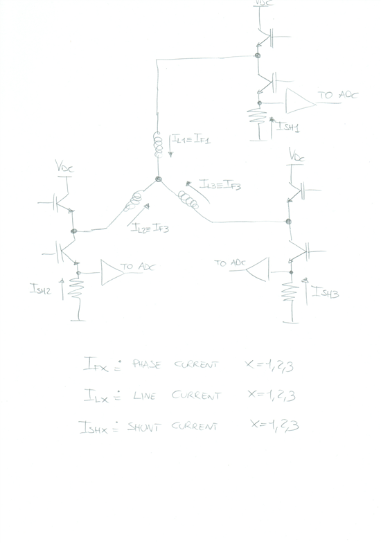
    If the motor is star-connected then, at certain moments:

    • phase current == line current == shunt current      ( "=="  equal;   "!=" disequal )
    Measured the shunt current, the phase current is obtained by direct equality.

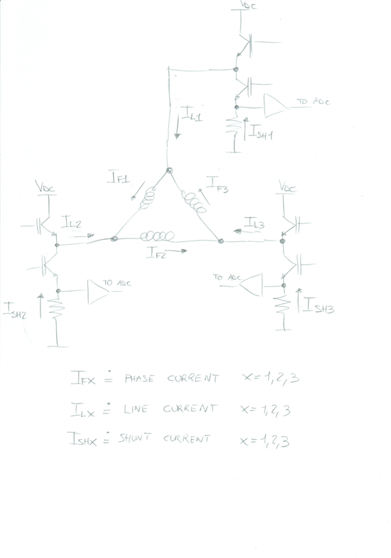
    If the motor is delta-connected then, at certain moments:

    • phase current != line current == shunt current       ( "=="  equal;   "!=" disequal )
    Measured the shunt current, the line current (and no the phase current) is obtained by direct equality.
    So the question is: how do I get the phase current in the case of a motor delta-connected?
  • Davide68542,

    due to the fact that in 3-phase-systems all voltages and currents are symmetrical, the simple calculation is:

    phase current in delta-connection is line current divided by sqrt(3): IFx = ILx / √3

    Regards,
    Robert