Other Parts Discussed in Thread: AM2434
Tool/software:
Hi Champs,
My customer is testing F28P65x SPI.
under mode 0, (POL=0, PHA=0) Controller sends 16bit and then F28P65x sends same data back.
I confirmed both Controller and F28P65x is set to mode 0.
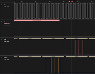
however, the result read on Controller is shifted, and the waveform from logic seems also not mode 0. Data came out like mode 3.
What can make this timing issue? I attached the code customer used, syscfg, and waveform.
Could you check?
Regards,
Ted
https://e2e.ti.com/cfs-file/__key/communityserver-discussions-components-files/171/spi_5F00_ex5_5F00_loopback_5F00_dma.syscfg
//#############################################################################
//
// FILE:   spi_ex5_loopback_dma.c
//
// TITLE:  SPI Digital Loopback with DMA
//
//! \addtogroup driver_example_list
//! <h1>SPI Digital Loopback with DMA</h1>
//!
//! This program uses the internal loopback test mode of the SPI module. Both
//! DMA interrupts and the SPI FIFOs are used. When the SPI transmit FIFO has
//! enough space (as indicated by its FIFO level interrupt signal), the DMA
//! will transfer data from global variable sData into the FIFO. This will be
//! transmitted to the receive FIFO via the internal loopback.
//!
//! When enough data has been placed in the receive FIFO (as indicated by its
//! FIFO level interrupt signal), the DMA will transfer the data from the FIFO
//! into global variable rData.
//!
//! When all data has been placed into rData, a check of the validity of the
//! data will be performed in one of the DMA channels' ISRs.
//!
//!  \note This example project has support for migration across our C2000
//!  device families. If you are wanting to build this project from launchpad
//!  or controlCARD, please specify in the .syscfg file the board you're using.
//!  At any time you can select another device to migrate this example.
//!
//! \b External \b Connections \n
//!  - None
//!
//! \b Watch \b Variables \n
//!  - \b sData - Data to send
//!  - \b rData - Received data
//!
//
//#############################################################################
//
//
//
// C2000Ware v5.04.00.00
//
// Copyright (C) 2024 Texas Instruments Incorporated - http://www.ti.com
//
// Redistribution and use in source and binary forms, with or without
// modification, are permitted provided that the following conditions
// are met:
//
//   Redistributions of source code must retain the above copyright
//   notice, this list of conditions and the following disclaimer.
//
//   Redistributions in binary form must reproduce the above copyright
//   notice, this list of conditions and the following disclaimer in the
//   documentation and/or other materials provided with the
//   distribution.
//
//   Neither the name of Texas Instruments Incorporated nor the names of
//   its contributors may be used to endorse or promote products derived
//   from this software without specific prior written permission.
//
// THIS SOFTWARE IS PROVIDED BY THE COPYRIGHT HOLDERS AND CONTRIBUTORS
// "AS IS" AND ANY EXPRESS OR IMPLIED WARRANTIES, INCLUDING, BUT NOT
// LIMITED TO, THE IMPLIED WARRANTIES OF MERCHANTABILITY AND FITNESS FOR
// A PARTICULAR PURPOSE ARE DISCLAIMED. IN NO EVENT SHALL THE COPYRIGHT
// OWNER OR CONTRIBUTORS BE LIABLE FOR ANY DIRECT, INDIRECT, INCIDENTAL,
// SPECIAL, EXEMPLARY, OR CONSEQUENTIAL DAMAGES (INCLUDING, BUT NOT
// LIMITED TO, PROCUREMENT OF SUBSTITUTE GOODS OR SERVICES; LOSS OF USE,
// DATA, OR PROFITS; OR BUSINESS INTERRUPTION) HOWEVER CAUSED AND ON ANY
// THEORY OF LIABILITY, WHETHER IN CONTRACT, STRICT LIABILITY, OR TORT
// (INCLUDING NEGLIGENCE OR OTHERWISE) ARISING IN ANY WAY OUT OF THE USE
// OF THIS SOFTWARE, EVEN IF ADVISED OF THE POSSIBILITY OF SUCH DAMAGE.
// $
//#############################################################################

//
// Included Files
//
#include "driverlib.h"
#include "device.h"
#include "board.h"

//
// Globals
//
uint16_t sData[128];                // Send data buffer
uint16_t rData[128];                // Receive data buffer

const void *destAddr = (const void *)rData;
const void *srcAddr = (const void *)sData;

// Place buffers in GSRAM
#pragma DATA_SECTION(sData, "DMA_TX_SECTION");
#pragma DATA_SECTION(rData, "DMA_RX_SECTION");

volatile uint16_t done = 0;         // Flag to set when all data transferred

//
// Function Prototypes
//
__interrupt void INT_mySPI0_RX_DMA_ISR(void);
__interrupt void INT_mySPI0_TX_DMA_ISR(void);

//
// Main
//
void main(void)
{
    uint16_t i;

    //
    // Initialize device clock and peripherals
    //
    Device_init();

    //
    // Disable pin locks and enable internal pullups.
    //
    Device_initGPIO();

    //
    // Initialize PIE and clear PIE registers. Disables CPU interrupts.
    //
    Interrupt_initModule();

    //
    // Initialize the PIE vector table with pointers to the shell Interrupt
    // Service Routines (ISR).
    //
    Interrupt_initVectorTable();

    //
    // Board initialization from SysConfig
    //
    Board_init();

    // Initialize the data buffers
    //
    for(i = 0; i < 128; i++)
    {
        sData[i] = i;
        rData[i]= 0;
    }

    //
    // Enable Global Interrupt (INTM) and realtime interrupt (DBGM)
    //
    EINT;
    ERTM;

    //
    // Start the DMA channels
    //
    DMA_startChannel(mySPI0_TX_DMA_BASE);
    DMA_startChannel(mySPI0_RX_DMA_BASE);

    //
    // Wait until the DMA transfer is complete
    //
    while(!done);

    //
    // When the DMA transfer is complete the program will stop here
    //
    ESTOP0;
}

//
// DMA Channel 5 ISR
//
__interrupt void INT_mySPI0_TX_DMA_ISR(void)
{
    DMA_stopChannel(mySPI0_TX_DMA_BASE);
    Interrupt_clearACKGroup(INT_mySPI0_TX_DMA_INTERRUPT_ACK_GROUP);
    return;
}

//
// DMA Channel 6 ISR
//
 __interrupt void INT_mySPI0_RX_DMA_ISR(void)
{
    uint16_t i;

    DMA_stopChannel(mySPI0_RX_DMA_BASE);
    Interrupt_clearACKGroup(INT_mySPI0_RX_DMA_INTERRUPT_ACK_GROUP);

    //
    // Check for data integrity
    //
    for(i = 0; i < 128; i++)
    {
        if (rData[i] != i)
        {
            // Something went wrong. rData doesn't contain expected data.
            ESTOP0;
        }
    }

    done = 1;
    return;
}


