This thread has been locked.

If you have a related question, please click the "Ask a related question" button in the top right corner. The newly created question will be automatically linked to this question.

TMS320F280049C: PRDLDSYNC bits are ineffective

Part Number: TMS320F280049C
Other Parts Discussed in Thread: SYSCONFIG

Tool/software:

Hello,

For my project I have configured 4 HRPWM channels and want to change the common period of these four wit the sync pulse.

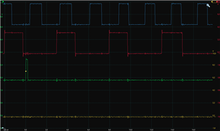
To try the effectiveness of the sync pulse I provide a SW pulse once to start the PWM.

My expectation was after a single SW pulse the PWM would start but then any try to change the TBPRD and TBPRDHR would be ineffective.

However, when I tried to change the TBPRD and TBPRDHR register from debugging view expression tab. I was able to do it and the frequency of the PWM changed for both TBPRD and TBPRDHR.

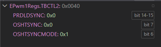
My related PWM configuration is such as below:


Also when I see the TRM I think there is a contracting description about this. Such as:

For the PRDLD bit of TBCTL register it is written that:
Active Period Reg Load from Shadow Select
0: The period register (TBPRD) is loaded from its shadow register
when the time-base counter, TBCTR, is equal to zero and/or a sync
event as determined by the TBCTL2[PRDLDSYNC] bit.
A write/read to the TBPRD register accesses the shadow register.
1: Immediate Mode (Shadow register bypassed): A write or read to
the TBPRD register accesses the active register.
Reset type: SYSRSn

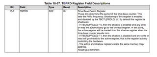
But for the TBPRD register, the explanation is:
Time Base Period Register
These bits determine the period of the time-base counter. This
sets the PWM frequency. Shadowing of this register is enabled
and disabled by the TBCTL[PRDLD] bit. By default this register is
shadowed.
- If TBCTL[PRDLD] = 0, then the shadow is enabled and any write
or read will automatically go to the shadow register. In this case,
the active register will be loaded from the shadow register when the
time-base counter equals zero. 

(It says update will be at CTR = 0 not according to PRDLDSYNC bits)


- If TBCTL[PRDLD] = 1, then the shadow is disabled and any write or
read will go directly to the active register, that is the register actively
controlling the hardware.
- The active and shadow registers share the same memory map
address.
Reset type: SYSRSn

Lastly, in the view expression tab I am able to see the PRDLD = 0 and PRDLDSYNC =2 

Any help would be highly appreciated.

  • Hi Gokhan,

    TBCTL[PRDLD] and TBCTL2[PRDLDSYNC] will determine the load mode of your configuration. The TBPRD register description doesn't mention TBCTL2 if that is set to non default value.

    But yes, you can use SYNC to load TBPRD once you have configured TBCTL2[PRDLDSYNC]

    Best,

    Ryan Ma

  • Thank you for your response.

    İf I understood correctly you say İ can change the period with only Sync pulse.

    However, i configured every PWM period shadow to active transfer with Sync pulse. Then in the run time, i fired a SW pulse once and never call Sync pulse again.

    But i could change the period with the debugging screen everytime after the first Sync.

    İ did not observe any pulse at the scope screen in normal case i do. So that means no Sync pulse.

  • Hi Gokhan,

    What is your SYNCIN source?

    Can you read the following register and clear after the first sync pulse comes?

    Best,

    Ryan Ma

  • Hi Ryan,

    Actually that is interesting.

    Except PWM1 the other PWMs SYNCI bit is 1. (PWM5 is the dummy PWM for generating ADC SOC trigger).

    I cleared those but still I am able to change the period of PWM. My code for that part is:


    EPWM_forceSyncPulse(myEPWM1_BASE);
    HRPWM_setSyncOutPulseMode(myEPWM1_BASE, EPWM_SYNC_OUT_PULSE_DISABLED);
    EPwm2Regs.TBSTS.bit.SYNCI = 1;
    EPwm3Regs.TBSTS.bit.SYNCI = 1;
    EPwm4Regs.TBSTS.bit.SYNCI = 1;
    EPwm5Regs.TBSTS.bit.SYNCI = 1;

  • Hi Gokhan,

    After clearing those bits, do they get set again? Are you only issuing once time sync event through software at the beginning?

    Best,

    Ryan Ma

  • Hi Gokhan,

    I just remembered. What you're seeing is the TBPRD of the shadow registers in the debugger view.

    Do you see your PWM output change when writing a new TBPRD value? If not, then that will confirm only seeing shadow register value.

    Best,

    Ryan Ma

  • Hi Ryan,

    No after clearing those bits they don't get set again.

    Yes as far as I know, I called this line once:

    EPWM_forceSyncPulse(myEPWM1_BASE);

    Then the software is not entering that part. Also, I dont see any sync pulse in oscilloscope where I set it trigged singe.  At the beginning I could  see the sync pulse as fallow:


    Debug moment means the moment I change the period value from debug screen. This image is the beginning. After this when change the period no sync value appears but frequency changes:


    The code that is run after debugging change are as follow:

    void updatePWMModule(void)
    {
    
    //1. According to the PWM_DEBUG_TEST macro, either the debug test code or the normal operation code will be run
    
    #if PWM_DEBUG_TEST
    // PWM variables from debugging tool
    
        if(PWM_update_debug)
        {
            GpioDataRegs.GPBSET.bit.GPIO57 = 1;
            final_phase_shift_12_deg  = pShift12_test;
            final_phase_shift_34_deg  = pShift34_test;
            Fsw_Hz = FREKANS_test;
            PWM_update_debug = 0;
            PWM_register_changed = 1;
            GpioDataRegs.GPBCLEAR.bit.GPIO57 = 1;
        }
    
    
    #endif
    
    //-------------------------------------------------------------------
    
    // 2. Period counter calculation
    //    Compute HRPWM period in timer counts:
    //  - Fsw_Hz        : switching frequency (Hz)
    //  - HRPWM resolution: 1 count = 78.125 ps
    //  - Period (s)    = 1.0 / Fsw_Hz
    //  - Period (ps)   = 1e12 / Fsw_Hz
    //  - period_cnt    = period_ps / 78.125 ps
    //                 = (1e12 / 78.125) / Fsw_Hz
    //                 = 1.28e10 / Fsw_Hz
        period_cnt = (uint32_t)(12800000000ULL / Fsw_Hz);
        duty_cnt   = (period_cnt >> 1);
    
    
    //-------------------------------------------------------------------
    
    // 3. Phase shift counter calculation
        // HRPWM phase shift has 2x resolution compared to period count (F280049C). (not exactly but we can go with this explanation)
        // So (degrees * period_cnt * 2) / 360 simplifies to (degrees * period_cnt) / 180
    
        // Phase shift between the legs of LLC1 (between High side mosfets)
        phase_shift_pwm1_to_pwm2 = (uint32_t)(((uint64_t)final_phase_shift_12_deg * period_cnt) / 180);
    
    
        // Phase shift between LLC phase 1 and 2 (between High side mosfets)
        phase_shift_pwm1_to_pwm3 = duty_cnt;   // 90° phase shift between PWM1 and PWM3: (duty_cnt = period_cnt / 2). Each count equals 39 ps in phase shift context (78 ps in period calculation).
    
        // Phase shift between two legs of LLC Phase 2
        phase_shift_pwm1_to_pwm4 = (uint32_t) ( ((uint64_t)final_phase_shift_34_deg * period_cnt) / 180 );
        phase_shift_pwm1_to_pwm4 = phase_shift_pwm1_to_pwm4 + phase_shift_pwm1_to_pwm3;  // final_phase_shift_34_deg + 90° ( 90° due to phase shift between LLC phase 1 & 2)
    
    //-------------------------------------------------------------------
    
    // 4. PWM4 T1 AQ qualifier settings based on the value of phase_shift_pwm1_to_pwm4.
        // If the value equals period/2 (i.e., duty_count), the T1 event must drive the output LOW
        // to avoid a missing pulse exactly at the synchronization moment.
        if (phase_shift_pwm1_to_pwm4 <= phase_shift_pwm1_to_pwm3 + 256) // Force LOW at T1 to avoid missing pulse
        {
            HRPWM_setActionQualifierAction(myEPWM4_BASE, EPWM_AQ_OUTPUT_A, EPWM_AQ_OUTPUT_LOW, EPWM_AQ_OUTPUT_ON_T1_COUNT_DOWN);
        }
        else
        {
            HRPWM_setActionQualifierAction(myEPWM4_BASE, EPWM_AQ_OUTPUT_A, EPWM_AQ_OUTPUT_NO_CHANGE, EPWM_AQ_OUTPUT_ON_T1_COUNT_DOWN);
        }
    
    //-------------------------------------------------------------------
    
    // 5.Phase shift variable assignment
    HRPWM_setPhaseShift(myEPWM2_BASE, phase_shift_pwm1_to_pwm2); // 1 count is 39 ps, -- for t ns delay argument should be 25.6*t. Also, the argument should not be greater than CMP value which are period/2
    HRPWM_setPhaseShift(myEPWM3_BASE, phase_shift_pwm1_to_pwm3);
    HRPWM_setPhaseShift(myEPWM4_BASE, phase_shift_pwm1_to_pwm4);
    //HRPWM_setPhaseShift(myEPWM1_BASE, 256); // for the 10ns offset we need to have 256 (1 count of TBPHS should be inserted for ePWM1)
    
    //-------------------------------------------------------------------
    
    // 6.Period and Duty Cycle variable assignment
    HRPWM_setTimeBasePeriod(myEPWM1_BASE, period_cnt);
    HRPWM_setCounterCompareValue(myEPWM1_BASE, HRPWM_COUNTER_COMPARE_A, duty_cnt);
    HRPWM_setCounterCompareValue(myEPWM1_BASE, HRPWM_COUNTER_COMPARE_B, duty_cnt); // Due to Using HRPWM and Active-high complementary dead band we need insert same CMP value for CMPB as CMPA
    
    //-------------------------------------------------------------------
    
    if(!Operation_start_flag)
        {
        // need to activate dead time here due to prevent PWM's to be high at the beginning
        HRPWM_setDeadBandDelayMode(myEPWM1_BASE, EPWM_DB_RED, true);
        HRPWM_setDeadBandDelayMode(myEPWM1_BASE, EPWM_DB_FED, true);
    
        HRPWM_setDeadBandDelayMode(myEPWM2_BASE, EPWM_DB_RED, true);
        HRPWM_setDeadBandDelayMode(myEPWM2_BASE, EPWM_DB_FED, true);
    
        HRPWM_setDeadBandDelayMode(myEPWM3_BASE, EPWM_DB_RED, true);
        HRPWM_setDeadBandDelayMode(myEPWM3_BASE, EPWM_DB_FED, true);
    
        HRPWM_setDeadBandDelayMode(myEPWM4_BASE, EPWM_DB_RED, true);
        HRPWM_setDeadBandDelayMode(myEPWM4_BASE, EPWM_DB_FED, true);
    
        HRPWM_setActionQualifierContSWForceAction(myEPWM1_BASE, EPWM_AQ_OUTPUT_A, EPWM_AQ_SW_DISABLED);
        HRPWM_setActionQualifierContSWForceAction(myEPWM1_BASE, EPWM_AQ_OUTPUT_B, EPWM_AQ_SW_DISABLED);
    
        HRPWM_setActionQualifierContSWForceAction(myEPWM2_BASE, EPWM_AQ_OUTPUT_A, EPWM_AQ_SW_DISABLED);
        HRPWM_setActionQualifierContSWForceAction(myEPWM2_BASE, EPWM_AQ_OUTPUT_B, EPWM_AQ_SW_DISABLED);
    
        HRPWM_setActionQualifierContSWForceAction(myEPWM3_BASE, EPWM_AQ_OUTPUT_A, EPWM_AQ_SW_DISABLED);
        HRPWM_setActionQualifierContSWForceAction(myEPWM3_BASE, EPWM_AQ_OUTPUT_B, EPWM_AQ_SW_DISABLED);
    
        HRPWM_setActionQualifierContSWForceAction(myEPWM4_BASE, EPWM_AQ_OUTPUT_A, EPWM_AQ_SW_DISABLED);
        HRPWM_setActionQualifierContSWForceAction(myEPWM4_BASE, EPWM_AQ_OUTPUT_B, EPWM_AQ_SW_DISABLED);
    
        HRPWM_setTimeBasePeriod(myEPWM1_BASE, period_cnt);
        HRPWM_setCounterCompareValue(myEPWM1_BASE, HRPWM_COUNTER_COMPARE_A, duty_cnt);
        HRPWM_setCounterCompareValue(myEPWM1_BASE, HRPWM_COUNTER_COMPARE_B, duty_cnt); // Due to Using HRPWM and Active-high complementary dead band we need insert same CMP value for CMPB as CMPA
    
        HRPWM_setPhaseShift(myEPWM1_BASE, 256); // for the 10ns offset we need to have 256 (1 count of TBPHS should be inserted for ePWM1)
    
    //    Interrupt_register(INT_myEPWM1, &INT_myEPWM1_ISR);
    //    Interrupt_enable(INT_myEPWM1);
        EPWM_forceSyncPulse(myEPWM1_BASE);
        HRPWM_setSyncOutPulseMode(myEPWM1_BASE, EPWM_SYNC_OUT_PULSE_DISABLED);
        EPwm2Regs.TBSTS.bit.SYNCI = 1;
        EPwm3Regs.TBSTS.bit.SYNCI = 1;
        EPwm4Regs.TBSTS.bit.SYNCI = 1;
        EPwm5Regs.TBSTS.bit.SYNCI = 1;
    
    //    EPWM_setSyncOutPulseMode(myEPWM1_BASE, EPWM_SYNC_OUT_PULSE_ON_COUNTER_ZERO);
    
        Operation_start_flag = 1;
    
        }
    
    //-------------------------------------------------------------------
    
    // 8. Sync pulse and interrupt enable with INT event counter reset
    
    
    //    EPWM_setSyncOutPulseMode(myEPWM1_BASE, EPWM_SYNC_OUT_PULSE_ON_COUNTER_ZERO);
    //    sync_enabled = 1;
    //    HRPWM_enableInterruptEventCountInit(myEPWM1_BASE);
    //    HRPWM_forceInterruptEventCountInit(myEPWM1_BASE);
    //    HRPWM_setSyncOutPulseMode(myEPWM1_BASE, EPWM_SYNC_OUT_PULSE_ON_COUNTER_COMPARE_C);
    
    
    //    HRPWM_enableInterrupt(myEPWM1_BASE);
    
    //    HRPWM_selectPeriodLoadEvent(myEPWM1_BASE, EPWM_SHADOW_LOAD_MODE_SYNC);
    
    }

  • Yes like I said I am observing the PWMs from oscilloscope. Their frequency change

  • Hi Gokhan,

    Apologize, I will have to sync up on this tomorrow. Got held up, but will be looking into this.

    Best,

    Ryan Ma

  • Hi Ryan, 
    Is there any update about this matter?

  • Hi Gokhan,

    Unfortunately I am unable to replicate this issue.

    Can you ensure that your Master PWM is set up with the following configuration for the One shot sync?

    OSHTSYNCMODE = 0x1 ensuring that Oneshot sync mode enabled.

    Only when OSHTSYNC gets set, should the software sync get propagated through to update the TBPRD register.

    It may be misleading to rely on the TBPRD in the register's view since that will show the shadow register value. 

    To verify if the loading only occurs on the SW Sync pulse, can you write a large number to TBBPRD and see that on the output PWM waveforms?

    Also ensure that your slave PWMs have phase shift enabled, and that the TBPRD load register is configured to only load on SYNC event.

    Best regards,

    Ryan Ma

  • Hi Gokhan,

    Here is a test case you can use to see the expected behavior.

    https://e2e.ti.com/cfs-file/__key/communityserver-discussions-components-files/171/empty_5F00_driverlib_5F00_project.7z

    Best,

    Ryan Ma

  • Hi Ryan,

    I have run the ex, without HRPWM it is working as intended. I mean without the sync pulse PWM2 period is not updated. However, when I added the HRPWM the problem occurs again

  • Hi Gokhan,

    I will have to take a look at this tomorrow with HRPWM enabled. 

    Best,

    Ryan Ma

  • Hi Gokhan,

    With and without HR enabled, I do not see my ePWM2 get updated unless I set the OSHTSYNC for ePWM1 to propagate the sync signal to ePWM2.

    Can you verify the following TBCTL + TBCTL2 for both ePWM1 and ePWM2? Please ignore EPWM1REGS.TBCTL2.SYNCOSELX that doesn't not affect the behavior.

    Best,

    Ryan Ma

  • Hi Gokhan,

    Please refer to this example which uses up/down count mode.

    https://e2e.ti.com/cfs-file/__key/communityserver-discussions-components-files/171/hrpwm_5F00_ex2_5F00_slider.7z

  • Hi Ryan,

    The problem with this example is, the ePWM2 HRPWM is not enabled actually. I need to enable "High Resolution Period Enable"  for EWPM2.
    After I selected it, there are various error popped up due to settings we need to do in HRPWM. 
    As a result, when I set HRPWM with the method sysconfig suggests the problem still occurs.
    I am sharing the SW here.

    hrpwm_ex2_slider_GB_edited.rar

  • Hi Gokhan,

    Thank you for the update. Apologize, I thought I had enabled HRPE for ePWM2.

    I, now, see the issue. I will have to get this simulated and replicated to figure out why enabling HRPE causes the TBPRD register to be loaded on every SYNC event instead of the one shot sync. Will keep this thread updated on my findings with our design team.

    Best,

    Ryan Ma

  • Hi Gokhan,

    Still waiting on our design team to get this simulated apologize for the delay. 

    Best regards,

    Ryan Ma

  • Hi Gokhan,

    We had a call today, will be updating this post once we get some more information. Apologize again for this delay.

    Best regards,

    Ryan Ma

  • Hi Ryan,
    Thank you for your effort.
    Still no progress?

  • Hi Gokhan,

    I am still trying to get this moved along. Apologize for the delay but still no progress. The team have the test case and are trying to run the test.

    Thank you for your patience.

    Best regards,

    Ryan Ma

  • Hi Gokhan,

    I should get an update tomorrow. Will keep this thread posted with possible work around. Again, apologize for this delay.

    Best regards,

    Ryan Ma

  • Hi Gokhan,

    Quick update, we are able to replicate the issue with the design team. Still need some more time root causing this issue. Thank you for your patience.

    Thank you,

    Ryan Ma

  • Hi Gokhan,

    We have filed this as a bug, and there is no work around for this if you're wanting to use sync to load the TBPRD registers when HRPE is enabled.

    The only work around would be to disable HRPE, and only have TBPRD without HR when using sync to load from shadow to active.

    You still can use CMPA/BHR for the fine resolution. 

    Best regards,

    Ryan Ma