This thread has been locked.

If you have a related question, please click the "Ask a related question" button in the top right corner. The newly created question will be automatically linked to this question.

TMS320F28P650DK: MCan RAM TX Buffer and API

Part Number: TMS320F28P650DK

Tool/software:

Dear support team,
I have worked with Mcan peripheral, and before approaching the questions I make an introduction.

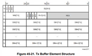
According to document SPRUIZ1B the TX Buffer Element Structure drawn on figure 35-21 page 5216 is for

  • classic CAN peripheral : FDF = 0
  • FD CAN peripheral : FDF = 1

According TI API and TI example "mcan_ex7_classic_transmit.c" , the function MCAN_writeMsgRam is used to fill the C structure MCAN_TxBufElement, whose data field is

uint16_t data[MCAN_MAX_PAYLOAD_BYTES];
#define MCAN_MAX_PAYLOAD_BYTES (64U)

The mentioned structure allocates on "RAM TX buffer", something that in "FD CAN" is called TX buffers and in "classic CAN peripheral" is called TX mailbox.
My consideration about the use of Mcan peripheral as "classic CAN peripheral" and driven by TI API is that: for every TX buffers allocated in RAM, a waste of ( 64 - 8 ) = 56 byte takes place.

Is my consideration correct ?
If yes, is there in TI API a TX BUFFER ELEMENT C structure, that has MAX_PAYLOAD_BYTES equals to 8, and its related C function to allocate it as "standard TX buffer element" ?
I would avoid the mentioned waste and using Mcan peripheral with API functions.

Thank you for your support,
Ettore

  • Good morning,
    today I have taken a look to the memory allocated by two TX Buffer Structure, with the setting
    classic CAN peripheral : FDF = 0.

    Counting the byte related to mentioned setting,
    4 byte for ID, RRT, XTD, ESI;
    3 byte for RES, DLC, BRS, FDF, RES, EFC,;
    1 byte for MM;
    8 byte of data;

    overall 16 byte.

    The first TX buffer starts at address 0x59130 and ends at 0x5913F.
    The second TX buffer starts at address 0x59140 and ends at 0x5914F.

    So it seems that the C compiler adjusts the size of data[MCAN_MAX_PAYLOAD_BYTES], the one belonging to the C structure MCAN_TxBufElement, according the TX buffer user setting.

    Am I wrong ?

    Thank you,
    Ettore

  • Hi Ettore,

    It is the MCAN module itself that allocates buffer/FIFO space depending on DLC.  It is not the C compiler.  Space allocation follows this element structure for Tx Buffer (same also applies to RX buffer):

    One row (Tx) is 4 bytes, and for classic CAN with DLC/payload of 8 bytes, one buffer element stops as the end of row T3 in the diagram.  The succeeding buffer element starts immediately on the next row and each element is 32-bit aligned.  This is an efficient way for MCAN to manage buffer allocation.

    Regards,

    Joseph