This thread has been locked.

If you have a related question, please click the "Ask a related question" button in the top right corner. The newly created question will be automatically linked to this question.

TMS320F28035-EP: SPI communication between MCU and DAC is not working

Part Number: TMS320F28035-EP

Tool/software:

Hi,

I am using TMS320F28035MPNTEP microcontroller and DAC DAC80504RTET. Trying to communicate using SPIA.

I tried to read Device ID of DAC from "Device ID register" and got garbage value. So started checking SPI signals. Chip select is not going low during data transfer. Below is the code and screenshot of signal

void spi_configureSPIAModule(void)
{
EALLOW;

GpioCtrlRegs.GPAMUX2.bit.GPIO16 = 1; // SPISIMOA (MOSI)
GpioCtrlRegs.GPAMUX2.bit.GPIO17 = 1; // SPISOMIA (MISO)
GpioCtrlRegs.GPAMUX2.bit.GPIO18 = 1; // SPICLKA (CLK)
GpioCtrlRegs.GPAMUX2.bit.GPIO19 = 1; // SPISTEA (CS)

GpioCtrlRegs.GPAPUD.bit.GPIO16 = 0;
GpioCtrlRegs.GPAPUD.bit.GPIO17 = 0;
GpioCtrlRegs.GPAPUD.bit.GPIO18 = 0;
GpioCtrlRegs.GPAPUD.bit.GPIO19 = 0;

// SPI configuration
SpiaRegs.SPICCR.bit.SPISWRESET = 0; // Hold SPI in reset
SpiaRegs.SPICCR.all = 0x0047; // 16-bit char, no loopback
SpiaRegs.SPICTL.all = 0x000E; // Master mode, enable TX, Falling edge data capture
SpiaRegs.SPIBRR = 0x007F; // SPI baud rate ~468.75kHz @ 60MHz
SpiaRegs.SPICCR.bit.SPISWRESET = 1; // Release SPI

SpiaRegs.SPIPRI.bit.FREE = 1; // Free run mode

EDIS;
}

void spi_writeToDAC(Uint8 regAddr, Uint16 value)
{
Uint8 cmdByte = 0;
Uint16 word1 = 0;
Uint16 word2 = 0;

// Bit 23 = 0 (Write), Bits 22–20 = 000 (reserved), Bits 19–16 = register address
cmdByte = (regAddr & 0x0F);

// Build 24-bit frame as two 16-bit writes (MSB first)
word1 = (cmdByte << 8) | ((value >> 8) & 0xFF); // First 16 bits: [Command][Data[15:8]]
word2 = (value & 0xFF) << 8; // Last 8 bits: [Data[7:0]] in upper byte

GpioDataRegs.GPACLEAR.bit.GPIO19 = 1; // CS low

// Send word1
SpiaRegs.SPITXBUF = word1;
while (SpiaRegs.SPISTS.bit.INT_FLAG == 0);
SpiaRegs.SPISTS.all = 0x0000;

// Send word2
SpiaRegs.SPITXBUF = word2;
while (SpiaRegs.SPISTS.bit.INT_FLAG == 0);
SpiaRegs.SPISTS.all = 0x0000;

GpioDataRegs.GPASET.bit.GPIO19 = 1; //CS high
}

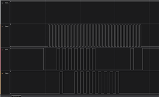
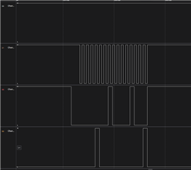
Captured below screenshot when I tried to write value 1 (spi_writeToDAC(0x08, 0x1);)

channel 0 is CS

Channel1 is CLK

Channel 2 is SPIA_MISO_DAC (SDO)

Channel 3 is SPIA_MOSI_uCtoDAC (SDI)

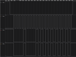
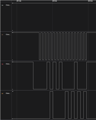
Captured below screenshot when I tried to write value 0x5555 (spi_writeToDAC(0x08, 0x5555);)

I am unable to find the issue with my code. Can you please help.

I tried configuring GPIO19 as GPIO instead of SPISTEA but did not get any signal on Channel 3 (SDI)

  • I changed SPICHAR, CLKPOLARITY, CLK_PHASE as given below and got the waveform as shown in screenshot. Still CS is not going low

    SPICCR:  1111

    SPICHAR: 0-3 : 16 bit word (F)

    SPILBK : 4 : Loop back disabled

    CLKPOLARITY : 6 := Data is output on rising edge and input on falling edge. When no SPI data is sent, SPICLK is at low level.

    The data input and output edges depend on the value of the CLOCK PHASE bit


    SPICTL : 0110

    SPIINTENA:  Disables the interrupt. (0)

    TALK : Enables transmission(1`)

    MASTER_SLAVE :  SPI is configured as a master.(1)

    CLK_PHASE : = Normal SPI clocking scheme, depending on the CLOCK POLARITY bit (SPICCR.6) (0)

    void spi_configureSPIAModule(void)
    {
        EALLOW;
    
        GpioCtrlRegs.GPAMUX2.bit.GPIO16 = 1; // SPISIMOA (MOSI)
        GpioCtrlRegs.GPAMUX2.bit.GPIO17 = 1; // SPISOMIA (MISO)
        GpioCtrlRegs.GPAMUX2.bit.GPIO18 = 1; // SPICLKA (CLK)
        GpioCtrlRegs.GPAMUX2.bit.GPIO19 = 1; // SPISTEA (CS)
    
        GpioCtrlRegs.GPAPUD.bit.GPIO16 = 0;
        GpioCtrlRegs.GPAPUD.bit.GPIO17 = 0;
        GpioCtrlRegs.GPAPUD.bit.GPIO18 = 0;
        GpioCtrlRegs.GPAPUD.bit.GPIO19 = 0;
    
        // SPI configuration
        SpiaRegs.SPICCR.bit.SPISWRESET = 0;   // Hold SPI in reset
        SpiaRegs.SPICCR.all = 0x000F;         // 16-bit, CPOL = 0, reset held
        SpiaRegs.SPICTL.all = 0x0006;         // Master, CPHA = 1
        SpiaRegs.SPIBRR = 0x007F;             // SPI baud rate ~468.75kHz @ 60MHz
        SpiaRegs.SPICCR.bit.SPISWRESET = 1;   // Release SPI
    
        SpiaRegs.SPIPRI.bit.FREE = 1;         // Free run mode
    
        EDIS;
    }
    
    void spi_writeToDAC(Uint8 regAddr, Uint16 value)
    {
        Uint8 cmdByte = 0;
        Uint16 word1 = 0;
        Uint16 word2 = 0;
    
        // Bit 23 = 0 (Write), Bits 22–20 = 000 (reserved), Bits 19–16 = register address
        cmdByte = (regAddr & 0x0F);
    
        // Build 24-bit frame as two 16-bit writes (MSB first)
        word1 = (cmdByte << 8) | ((value >> 8) & 0xFF);   // First 16 bits: [Command][Data[15:8]]
        word2 = (value & 0xFF) << 8;                      // Last 8 bits: [Data[7:0]] in upper byte
    
        GpioDataRegs.GPACLEAR.bit.GPIO19 = 1; // CS low
    
        // Send word1
        SpiaRegs.SPITXBUF = word1;
        while (SpiaRegs.SPISTS.bit.INT_FLAG == 0);
        SpiaRegs.SPISTS.all = 0x0000;
    
        // Send word2
        SpiaRegs.SPITXBUF = word2;
        while (SpiaRegs.SPISTS.bit.INT_FLAG == 0);
        SpiaRegs.SPISTS.all = 0x0000;
    
        GpioDataRegs.GPASET.bit.GPIO19 = 1; //CS high
    }

  • I'm uncertain why CS is not going low during the normal case, but when you're trying to manually control it, note that in your spi_configureSPIAModule() func, you're setting GPAMUX2.GPIO19 = 1, meaning that GPIO19 is not manually controllable, instead controlled by the SPI.

    Try changing that configuration and seeing if manual control of IO19 is possible. If it is not, then there may be HW issues- make sure IO19 is not somehow grounded in your circuit.

    Regards,
    Jason Osborn

  • Thank You for your reply Jason,

    CS is working now. As of now waveform looks good