Part Number: TMS320F28379D
Other Parts Discussed in Thread: C2000WARE
Tool/software:
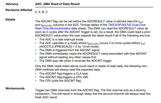
I want to collect a voltage signal and transfer it to a specified array with DMA. After following the routine modification, I found that the program could not trigger the end of transfer interruption for DMA. I tried to clear the ADC's interrupt flag after each ADC transition, and the DMA was able to transfer the data normally and enter the end interrupt. However, I saw in the user manual that DMA will actively signal an interrupt purge to the interrupt source.
I'm wondering why my program didn't clear the ADC's interrupt flag. There is no code to clear ADC interrupts or even enable the corresponding interrupt function in the DMA transfer ADC result routine, but the program works normally. Here's my code, begging for help.
#include "driverlib.h"
#include "device.h"
#include "F28x_Project.h"

#define RESULTS_BUFFER_SIZE     256

void initADC(void);
void initEPWM(void);
void initADCSOC(void);
void initializeDMA(void);
void configureDMAChannels(void);

__interrupt void adcA1ISR(void);
__interrupt void dmach1ISR(void);

#pragma DATA_SECTION(adcAResults, "ramgs0");
uint16_t adcAResults[RESULTS_BUFFER_SIZE];
volatile uint16_t bufferFull;

void main(void)
{

    // Initialize device clock and peripherals
    Device_init();

    // Disable pin locks and enable internal pullups.
    Device_initGPIO();

    /*
    #ifdef _STANDALONE
    #ifdef _FLASH
        // Send boot command to allow the CPU2 application to begin execution
        Device_bootCPU2(C1C2_BROM_BOOTMODE_BOOT_FROM_FLASH);
    #else
        // Send boot command to allow the CPU2 application to begin execution
        Device_bootCPU2(C1C2_BROM_BOOTMODE_BOOT_FROM_RAM);
    #endif // _FLASH
    #endif // _STANDALONE
    */

    // Initialize PIE and clear PIE registers. Disables CPU interrupts.
    Interrupt_initModule();

    // Initialize the PIE vector table with pointers to the shell Interrupt
    // Service Routines (ISR).
    Interrupt_initVectorTable();

    // Interrupts that are used in this example are re-mapped to ISR functions
    // found within this file.
    Interrupt_register(INT_ADCA1, &adcA1ISR);

    // ISR for DMA ch1 - occurs when DMA transfer is complete
    Interrupt_register(INT_DMA_CH1, &dmach1ISR);

    // Enable specific PIE & CPU interrupts:
    // DMA interrupt - Group 7, interrupt 1
    Interrupt_enable(INT_DMA_CH1);

    // Set up the ADC and the ePWM and initialize the SOC
    initADC();
    initEPWM();
    initADCSOC();

    // Initialize the DMA & configure DMA channels 1
    initializeDMA();
    configureDMAChannels();

    bufferFull = 0;

    // Enable ADC interrupt
    Interrupt_enable(INT_ADCA1);

    // Clearing all pending interrupt flags
    DMA_clearTriggerFlag(DMA_CH1_BASE);   // DMA channel 1
    HWREGH(ADCA_BASE + ADC_O_INTFLGCLR) = 0x1U; // ADCA

    // Enable Global Interrupt (INTM) and realtime interrupt (DBGM)
    EINT;
    ERTM;

    for(;;)
    {
        // Start DMA
        DMA_startChannel(DMA_CH1_BASE);

        // Start ePWM1, enabling SOCA and putting the counter in up-count mode
        EPWM_enableADCTrigger(EPWM1_BASE, EPWM_SOC_A);
        EPWM_setTimeBaseCounterMode(EPWM1_BASE, EPWM_COUNTER_MODE_UP);

        // Wait while ePWM1 causes ADC conversions which then cause interrupts.
        // When the results buffer is filled, the bufferFull flag will be set.
        while(bufferFull == 0)
        {

        }
        bufferFull = 0;     // Clear the buffer full flag

        // Stop ePWM1, disabling SOCA and freezing the counter
        EPWM_disableADCTrigger(EPWM1_BASE, EPWM_SOC_A);
        EPWM_setTimeBaseCounterMode(EPWM1_BASE, EPWM_COUNTER_MODE_STOP_FREEZE);

        // Software breakpoint. At this point, conversion results are stored in
        // adcAResults.
        // Hit run again to get updated conversions.
        ESTOP0;
    }
}


// Function to configure and power up ADCA.
void initADC(void)
{
    // Set ADCDLK divider to /4
    ADC_setPrescaler(ADCA_BASE, ADC_CLK_DIV_4_0);

    // Set resolution and signal mode (see #defines above) and load
    // corresponding trims.
    ADC_setMode(ADCA_BASE, ADC_RESOLUTION_12BIT, ADC_MODE_SINGLE_ENDED);

    // Set pulse positions to late
    ADC_setInterruptPulseMode(ADCA_BASE, ADC_PULSE_END_OF_CONV);

    // Power up the ADC and then delay for 1 ms
    ADC_enableConverter(ADCA_BASE);
    DEVICE_DELAY_US(1000);
}

// Function to configure ePWM1 to generate the SOC.
void initEPWM(void)
{
    // Disable SOCA
    EPWM_disableADCTrigger(EPWM1_BASE, EPWM_SOC_A);

    // Configure the SOC to occur on the first up-count event
    EPWM_setADCTriggerSource(EPWM1_BASE, EPWM_SOC_A, EPWM_SOC_TBCTR_U_CMPA);
    EPWM_setADCTriggerEventPrescale(EPWM1_BASE, EPWM_SOC_A, 1);

    // Set the compare A value to 1000 and the period to 1999
    // Assuming ePWM clock is 100MHz, this would give 50kHz sampling
    // 50MHz ePWM clock would give 25kHz sampling, etc.
    // The sample rate can also be modulated by changing the ePWM period
    // directly (ensure that the compare A value is less than the period).
    EPWM_setCounterCompareValue(EPWM1_BASE, EPWM_COUNTER_COMPARE_A, 49);
    EPWM_setTimeBasePeriod(EPWM1_BASE, 99);

    // Set the local ePWM module clock divider to /1
    EPWM_setClockPrescaler(EPWM1_BASE,
                           EPWM_CLOCK_DIVIDER_1,
                           EPWM_HSCLOCK_DIVIDER_1);

    // Freeze the counter
    EPWM_setTimeBaseCounterMode(EPWM1_BASE, EPWM_COUNTER_MODE_STOP_FREEZE);
}

// Function to configure ADCA's SOC0 to be triggered by ePWM1.
void initADCSOC(void)
{
    // Configure SOC0 of ADCA to convert pin A1. The EPWM1SOCA signal will be
    // the trigger.
    // - For 12-bit resolution, a sampling window of 15 (75 ns at a 200MHz
    //   SYSCLK rate) will be used.
    // - NOTE: A longer sampling window will be required if the ADC driving
    //   source is less than ideal (an ideal source would be a high bandwidth
    //   op-amp with a small series resistance). See TI application report
    //   SPRACT6 for guidance on ADC driver design.
    ADC_setupSOC(ADCA_BASE, ADC_SOC_NUMBER0, ADC_TRIGGER_EPWM1_SOCA,
                 ADC_CH_ADCIN0, 15);

    // Set SOC0 to set the interrupt 1 flag. Enable the interrupt and make
    // sure its flag is cleared.
    ADC_setInterruptSource(ADCA_BASE, ADC_INT_NUMBER1, ADC_SOC_NUMBER0);
    ADC_enableInterrupt(ADCA_BASE, ADC_INT_NUMBER1);
    ADC_clearInterruptStatus(ADCA_BASE, ADC_INT_NUMBER1);
}

void initializeDMA(void)
{
    // Perform a hard reset on DMA
    DMA_initController();

    // Allow DMA to run free on emulation suspend
    DMA_setEmulationMode(DMA_EMULATION_FREE_RUN);
}

void configureDMAChannels(void)
{
    // DMA channel 1 set up for ADCA
    DMA_configAddresses(DMA_CH1_BASE, (uint16_t *)&adcAResults,
                        (uint16_t *)(ADCARESULT_BASE+ADC_SOC_NUMBER0));

    DMA_configBurst(DMA_CH1_BASE, 1, 0, 0);
    DMA_configTransfer(DMA_CH1_BASE, RESULTS_BUFFER_SIZE, 0, 1);
    DMA_configMode(DMA_CH1_BASE, DMA_TRIGGER_ADCA1,
                  (DMA_CFG_ONESHOT_DISABLE | DMA_CFG_CONTINUOUS_DISABLE |
                   DMA_CFG_SIZE_16BIT));

    DMA_enableTrigger(DMA_CH1_BASE);
    DMA_disableOverrunInterrupt(DMA_CH1_BASE);
    DMA_setInterruptMode(DMA_CH1_BASE, DMA_INT_AT_END);
    DMA_enableInterrupt(DMA_CH1_BASE);
}

// ADC A Interrupt 1 ISR
__interrupt void adcA1ISR(void)
{
    // Add the latest result to the buffer
    //adcAResults[index++] = ADC_readResult(ADCARESULT_BASE, ADC_SOC_NUMBER0);

    // Clear the interrupt flag
    ADC_clearInterruptStatus(ADCA_BASE, ADC_INT_NUMBER1);

    // Check if overflow has occurred
    /*
    if(true == ADC_getInterruptOverflowStatus(ADCA_BASE, ADC_INT_NUMBER1))
    {
        ADC_clearInterruptOverflowStatus(ADCA_BASE, ADC_INT_NUMBER1);
        ADC_clearInterruptStatus(ADCA_BASE, ADC_INT_NUMBER1);
    }
    */

    // Acknowledge the interrupt
    Interrupt_clearACKGroup(INTERRUPT_ACK_GROUP1);

}

#pragma CODE_SECTION(dmach1ISR, ".TI.ramfunc");
__interrupt void dmach1ISR(void)
{
    bufferFull = 1;

    // Acknowledge interrupt
    Interrupt_clearACKGroup(INTERRUPT_ACK_GROUP7);
}