This thread has been locked.

If you have a related question, please click the "Ask a related question" button in the top right corner. The newly created question will be automatically linked to this question.

TMS320F28335: Swap the values of EPW1A with EPW1B, Similarly EPW2A with EPW2B

Part Number: TMS320F28335

Tool/software:

Dear TI members,

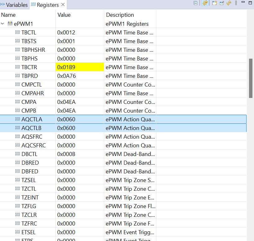
I follow an example code of EPWM generation. By adding a factor duty & TPWM variable(like TPWM =5357, duty = 0.46) set by me in the code, I get the frequency around 28Khz, but the duty cycles from 

EPWM1A is on GPIO0 = 54%

EPWM1B is on GPIO1 = 46%

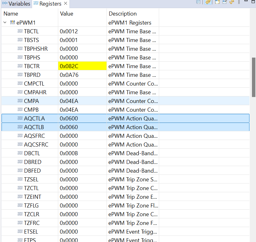
I would like to change or swap the duty cycle values so that I can get the results on EPWM1A on GPIO0 and EPWM1B on GPIO1 like this:

EPWM1A is on GPIO0 = 46%

EPWM1B is on GPIO1 = 54%

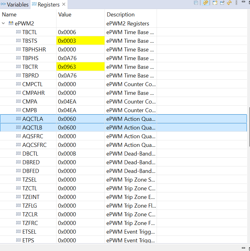
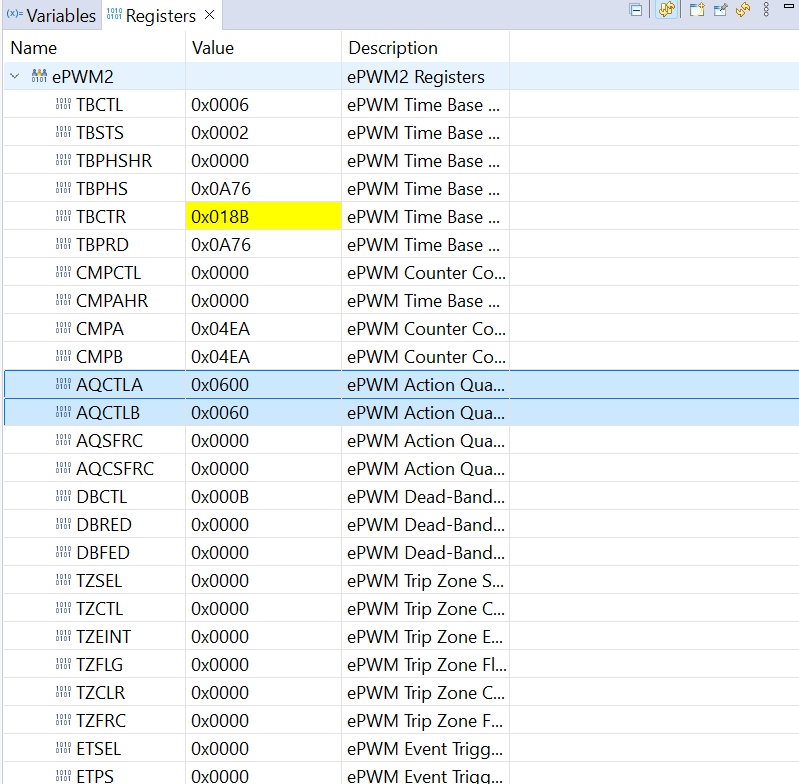
The same procedure for EPWM2 for swapping the values(EPWM2A change to EPWM2B) is required. 

Please suggest how I can change in the code.

Please find attached code:

Thanks

Regards

Arsalan

  • Hello,

    If you want to swap your outputs, you could just swap Action Qualifier events on EPWM1A and EPWMB. (i.e EPwm1Regs.AQCTLA.all = 0x0600; EPwm1Regs.AQCTLB.all = 0x0060;)

  • Hi Stevan, 

    Thanks for your reply.

    By changing the value(EPwm1Regs.AQCTLA, EPwm1Regs.AQCTLB)  in the code below, it keeps the same duty cycle value as before (NO CHANGE/Swap occurred) in both EPWM1 & EPWM2. I have a working code for serially transferring TPWM and Duty values. which receives the values externally, that I tested before, and it gets exact TPWM and Duty values externally. The issue comes in swapping the duty cycle values. Please check the attached code:

    Before Changes:

    After Changes:

    Results checked through the Oscilloscope, same as before changes:

    EPWM1A is on GPIO0 = 54%

    EPWM1B is on GPIO1 = 46% 

    EPWM2A is on GPIO2 = 54%

    EPWM2B is on GPIO3 = 46% 

    Please find the attached code 

    We need/require

    EPWM1A is on GPIO0 = 46%

    EPWM1B is on GPIO1 = 54%

     EPWM2A is on GPIO2 = 46%

    EPWM2B is on GPIO3 = 54%


    Please suggest this accordingly.

    Regards

    Arsalan

  • Hello Arsalan,

     It is strange how you get 54% duty cycle on PWMA and 46% on PWMB if your CMPA = CMPB = 0.46 * PERIOD, and with the way you configured your action qualifiers.

    When I took another look at your implementation, this happened because you used inverted mode in Dead-Band submodule. When you use that your EPWMB will always be complementary to EPWMA. 

    So, there is many ways to achieve your desired duty cycle. If you use inverted mode (EPwm1Regs.DBCTL.bit.POLSEL = 2); Then you don't need to configure CMPB and ACTLB at all. You could just set your Duty = 0.54, and use CMPA and ACQTLA.

    Or without inverted mode you can put Duty = 0.54 and just use CMPA. Then for PWMB you can clear on count up and set on CMPA count down (AQCTLB). Hope this helps.