Part Number: LAUNCHXL-F28379D
Other Parts Discussed in Thread: SYSCONFIG, C2000WARE
Tool/software:
Hello,
I am trying to read data from an ADC and transmit that data via SPI using a LAUNCHXL-F28379D. I have gotten both functions to work individually, but I am having some trouble doing both at the same time. I am using CCS 20.1.1.
I am operating the LaunchPad as a peripheral, and I have an ISR which runs every time a message is received via MOSI (INT_mySPI0_RX_ISR). This ISR reads the MOSI data then transmits a new set of data via MISO. The data on MISO is where I am trying to send the ADC data.
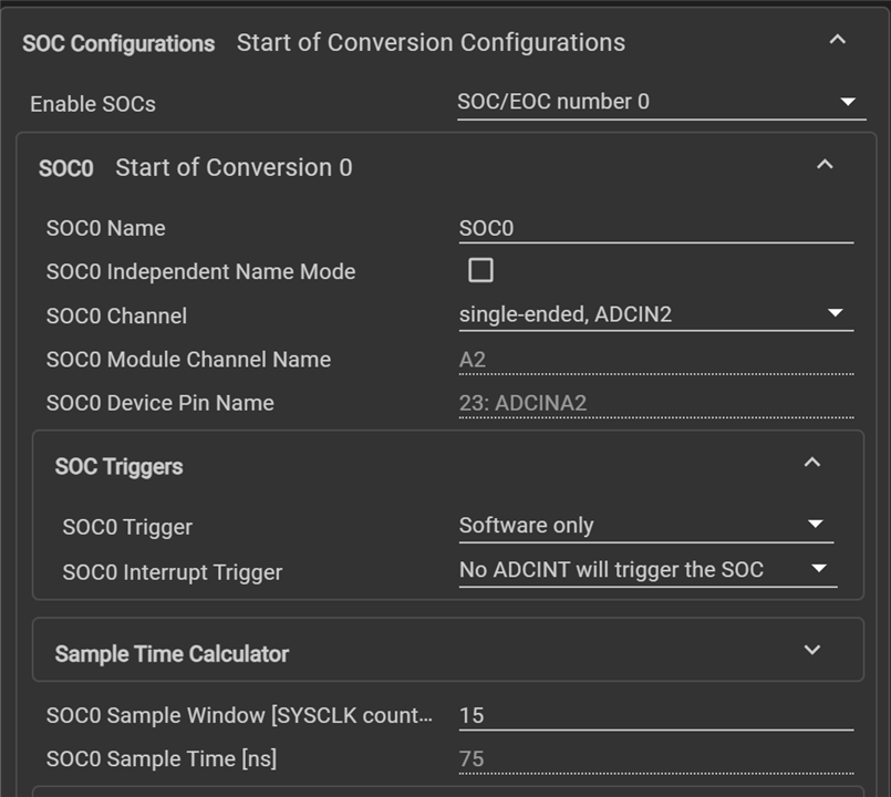
To achieve this, I have added an ADC_readResult() function inside INT_mySPI0_RX_ISR, as well as configured the .sysconfig file to allow for software interrupts. However, after numerous attempts with slightly different settings, I am not able to properly read the ADC data. Every time, I read 0 (zero), even when I am certain I am applying a non-zero voltage to the correct pin with an external power supply.
Ideally, I would like to read the ADC value in INT_mySPI0_RX_ISR to minimize the number of interrupts happening. Is this possible, or do I need a separate ISR for ADC? If I need a separate ISR, how do I configure the timing to match with my SPI transmissions to not waste computing resources?
I have attached my .c file and .sysconfig file (as a text file). Thank you.
//#############################################################################
//
// FILE:   spi_ex1_loopback.c
//
// TITLE:  SPI Digital Loopback
//
//! \addtogroup driver_example_list
//! <h1>SPI Digital Loopback</h1>
//!
//! This program uses the internal loopback test mode of the SPI module. This
//! is a very basic loopback that does not use the FIFOs or interrupts. A
//! stream of data is sent and then compared to the received stream.
//! The pinmux and SPI modules are configure through the sysconfig file.
//!
//! The sent data looks like this: \n
//!  0000 0001 0002 0003 0004 0005 0006 0007 .... FFFE FFFF 0000
//!
//! This pattern is repeated forever.
//!
//! \b External \b Connections \n
//!  - None
//!
//! \b Watch \b Variables \n
//!  - \b sData - Data to send
//!  - \b rData - Received data
//!
//
//#############################################################################
//
//
// $Copyright:
// Copyright (C) 2013-2024 Texas Instruments Incorporated - http://www.ti.com/
//
// Redistribution and use in source and binary forms, with or without
// modification, are permitted provided that the following conditions
// are met:
//
//   Redistributions of source code must retain the above copyright
//   notice, this list of conditions and the following disclaimer.
//
//   Redistributions in binary form must reproduce the above copyright
//   notice, this list of conditions and the following disclaimer in the
//   documentation and/or other materials provided with the
//   distribution.
//
//   Neither the name of Texas Instruments Incorporated nor the names of
//   its contributors may be used to endorse or promote products derived
//   from this software without specific prior written permission.
//
// THIS SOFTWARE IS PROVIDED BY THE COPYRIGHT HOLDERS AND CONTRIBUTORS
// "AS IS" AND ANY EXPRESS OR IMPLIED WARRANTIES, INCLUDING, BUT NOT
// LIMITED TO, THE IMPLIED WARRANTIES OF MERCHANTABILITY AND FITNESS FOR
// A PARTICULAR PURPOSE ARE DISCLAIMED. IN NO EVENT SHALL THE COPYRIGHT
// OWNER OR CONTRIBUTORS BE LIABLE FOR ANY DIRECT, INDIRECT, INCIDENTAL,
// SPECIAL, EXEMPLARY, OR CONSEQUENTIAL DAMAGES (INCLUDING, BUT NOT
// LIMITED TO, PROCUREMENT OF SUBSTITUTE GOODS OR SERVICES; LOSS OF USE,
// DATA, OR PROFITS; OR BUSINESS INTERRUPTION) HOWEVER CAUSED AND ON ANY
// THEORY OF LIABILITY, WHETHER IN CONTRACT, STRICT LIABILITY, OR TORT
// (INCLUDING NEGLIGENCE OR OTHERWISE) ARISING IN ANY WAY OUT OF THE USE
// OF THIS SOFTWARE, EVEN IF ADVISED OF THE POSSIBILITY OF SUCH DAMAGE.
// $
//#############################################################################

//
// Included Files
//
#include "driverlib.h"
#include "device.h"
#include "board.h"

//
// Interrupt prototypes
//
__interrupt void INT_mySPI0_RX_ISR(void);
__interrupt void INT_mySPI0_TX_ISR(void);

//
// Global variables
//
uint16_t sData = 374;                  // Send data
//uint16_t sDataInc = 0;
uint16_t rData = 0;                  // Receive data

//
// Main
//
void main(void)
{
    //
    // Initialize device clock and peripherals
    //
    Device_init();

    //
    // Disable pin locks and enable internal pullups.
    //
    Device_initGPIO();

    //
    // Initialize PIE and clear PIE registers. Disables CPU interrupts.
    //
    Interrupt_initModule();

    //
    // Initialize the PIE vector table with pointers to the shell Interrupt
    // Service Routines (ISR).
    //
    Interrupt_initVectorTable();

    //
    // Board initialization
    //
    Board_init();

    ADC_enableConverter(ADCA_BASE);

    //
    // Enable Global Interrupt (INTM) and realtime interrupt (DBGM)
    //
    EINT;
    ERTM;

    //
    // Loop forever. Suspend or place breakpoints to observe the buffers.
    //
    while(1)
    {

    }
}

//
// Data reception ISR
//
__interrupt void INT_mySPI0_RX_ISR(void)
{
    // Block until data is received and then return it
    rData = SPI_readDataBlockingNonFIFO(mySPI0_BASE);

    // Transmit data
    sData = ADC_readResult(myADCA_RESULT_BASE, myADCA_SOC0);
    SPI_writeDataNonBlocking(mySPI0_BASE, sData);

    Interrupt_clearACKGroup(INTERRUPT_ACK_GROUP6);
}

//
// Data transmission ISR
//
__interrupt void INT_mySPI0_TX_ISR(void)
{
    Interrupt_clearACKGroup(INTERRUPT_ACK_GROUP6);
}

//
// End File
//
/**
 * These arguments were used when this file was generated. They will be automatically applied on subsequent loads
 * via the GUI or CLI. Run CLI with '--help' for additional information on how to override these arguments.
 * @cliArgs --device "F2837xD" --part "F2837xD_100PTP" --package "F2837xD_100PTP" --context "CPU1" --product "C2000WARE@5.04.00.00"
 * @v2CliArgs --device "TMS320F28375D" --package "100PTP" --context "CPU1" --product "C2000WARE@5.04.00.00"
 * @versions {"tool":"1.23.0+4000"}
 */

/**
 * Import the modules used in this configuration.
 */
const adc  = scripting.addModule("/driverlib/adc.js", {}, false);
const adc1 = adc.addInstance();
const spi  = scripting.addModule("/driverlib/spi.js", {}, false);
const spi1 = spi.addInstance();

/**
 * Write custom configuration values to the imported modules.
 */
adc1.adcClockPrescaler  = "ADC_CLK_DIV_4_0";
adc1.$name              = "myADCA";
adc1.soc0SampleWindow   = 15;
adc1.registerInterrupts = ["1"];
adc1.soc0Channel        = "ADC_CH_ADCIN2";
adc1.useInterrupts      = false;
adc1.enabledSOCs        = ["ADC_SOC_NUMBER0"];

spi1.$name                    = "mySPI0";
spi1.emulationMode            = "SPI_EMULATION_FREE_RUN";
spi1.enabledInterrupts        = ["SPI_INT_RX_DATA_TX_EMPTY"];
spi1.registerInterrupts       = true;
spi1.useFifo                  = false;
spi1.spi.$assign              = "SPIA";
spi1.spi.spi_picoPin.$assign  = "GPIO58";
spi1.spi.spi_pociPin.$assign  = "GPIO59";
spi1.spi.spi_clkPin.$assign   = "GPIO60";
spi1.spi.spi_ptePin.$assign   = "GPIO61";
spi1.picoQual.$name           = "myGPIOQUAL0";
spi1.pociQual.$name           = "myGPIOQUAL1";
spi1.clkQual.$name            = "myGPIOQUAL2";
spi1.pteQual.$name            = "myGPIOQUAL3";
spi1.spiRXInt.enableInterrupt = true;
spi1.spiTXInt.enableInterrupt = true;