This thread has been locked.

If you have a related question, please click the "Ask a related question" button in the top right corner. The newly created question will be automatically linked to this question.

TMS320F28384D: CAN FD Responses from Slave Control Cards Go Missing (Not Visible) on CAN FD Bus Analyzer & in Master

Part Number: TMS320F28384D


Tool/software: CCS, CAN FD Analyzer

Hey,

My project requires communication between a Master and 9 Slaves via CAN FD. Data from Master (ID: 10, 0xA) to all Slaves (IDs 1, 2, 3... 9) is being broadcasted and in return, I programmed the Slaves to respond with a single-frame acknowledgement.

While testing, when there's the Master and 4 Slaves on the CAN FD bus, in response to the broadcasted data, I only observe a maximum of two Slaves that respond with an acknowledgement frame on the CAN FD Bus Analyzer Software Tool.

I'm sure that the other two Slaves are receiving the data since I have a counter that runs after reception, I also observed that the response (transmission from Slave to Master after receiving data from Master) frame is being structured but I can't tell if its actually being sent.

Individually, if there's only the Master, a Slave and the CAN FD Analyzer, the acknowledgement is being sent as seen on the CAN FD Software Tool, but only when there's multiple Slaves, I'm facing this issue. 

Master Broadcast Data ID configuration:

txMsg[0][BROADCAST_CONTROLDATA].id = (MCU << 12) | (0 << 8) | (BROADCAST_CONTROLDATA << 4) | (1);
txMsg[0][BROADCAST_CONTROLDATA].rtr = 0U;
txMsg[0][BROADCAST_CONTROLDATA].xtd = 1;
txMsg[0][BROADCAST_CONTROLDATA].esi = 0U;
txMsg[0][BROADCAST_CONTROLDATA].dlc = 15;
txMsg[0][BROADCAST_CONTROLDATA].brs = 1U;
txMsg[0][BROADCAST_CONTROLDATA].fdf = 1U;
txMsg[0][BROADCAST_CONTROLDATA].efc = 1U;
txMsg[0][BROADCAST_CONTROLDATA].mm = 0xAAU;

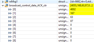
(All the parameters are the same for both Master and Slave except for those that are specified below for Slave's acknowledgement)

txMsg_Config_Para_st.id = (Lcu_node_id << 12) | (MCU_ID << 8) | (BROADCAST_CONTROLDATA << 4) |(6);
txMsg_Config_Para_st.data[0] = 0x06;
txMsg_Config_Para_st.dlc = 4U;

Data bit-rate is at 5 Mbps while the arbitration bit-rate is at 500 Kbps. I'm of the assumption that the bus is too busy to accommodate more than 2 LCUs which is why all 4 acknowledgements sent by 4 Slaves on the bus currently aren't always read by the Master. I have another counter declared as an array in the Master's program whose element's increment when the master receives the particular Slave's acknowledgement.

 With 4 Slaves on the bus, all of which are programmed the same, I get different number of acknowledgements. There is also a lot of randomness in the reception of acknowledgements in the Master control card. 


Please let me know if I can provide additional data should you need it to resolve this issue.

Best, 

Nalin P.

  • Hi Nalin,

    Is there a way for you to do a live debug on the receiving nodes (at least one of them) and also connect it to CCS to monitor if there are any errors during frame reception and transmission?  Maybe monitor flags for bus off (if there are way too many errors) and error register flags/counters? From your description on randomness of reception, maybe good to scope the CAN bus to check on signal quality.  The newer scopes (even the Pico scopes) have the ability to decode CAN/CAN-FD signals so it will be a useful tool in checking signal quality especially that you are running at the corner of the maximum data rate of 5Mbps.

    I would start first with checking the signal quality on the but since there are several nodes that are involved and any node may be contributing to signal degradation.

    Regards,

    Joseph 

  • Hey Joseph

    Apologies for the late reply  

    Is there a way for you to do a live debug on the receiving nodes (at least one of them) and also connect it to CCS to monitor if there are any errors during frame reception and transmission?

    I have had 2 receiving nodes (Local Units / Slaves) under debug while there were 4 receiving nodes on the bus. I could confirm that the nodes were receiving the broadcasted data which was being loaded into its local variables successfully, the response (acknowledgement frame) was also being manufactured as programmed. What I can't confirm is if the Slaves are responding with the acknowledgement frame and I can't see it on the MCU expression window (array counter increments for every Slave responding) or... if the Slaves aren't responding at all.


    In this picture, not all the Slaves are responding all the time.

    Maybe monitor flags for bus off (if there are way too many errors) and error register flags/counters?

    I'll check for the bus-off again, with multiple slaves on the bus. As per my knowledge, I haven't observed any error register flags/counters being set. Could you be more specific as to what register flags/counters I should keep an eye on?

    From your description on randomness of reception, maybe good to scope the CAN bus to check on signal quality.

    The Slaves responses are random but I have never observed every slave that are kept on the bus respond completely. I will check the bus on a scope and get back here.

    Best,

    Nalin

  • Hi Nalin,

    Inspect the MCAN_PSR register contents,  There are different fields that you can examine to see if there are any anomalies lfrom LEC (last error code), BO for bus off condition and the other fields which may help indicate what the issue is.  Yes, good to check on the bus waveforms as that would give you also an indication of bus activity and its condition.

    Regards,

    Joseph

  • Hi Joseph,

    Thank you for confirming the registers, I did verify them before and no error was being set. I have since updated the MCAN_CCCR.DAR (Disable Automatic Re-transmission) to 0 from 1 and the system is working. As per the project, I needed 9 nodes to respond with an acknowledgement to the main unit and they're all responding now.

    I don't see any error registers, flags or the counters being set either. I appreciate your quick responses. Please keep the question for now, I'll keep the system under test over the duration of the weekend and I'll confirm first thing Monday morning local time. 

    Thank you again! Have a great weekend.

    Best,

    Nalin

  • Hi Nalin,

    Ok, will wait for your weekend checkout.  I'm still unsure why disabling automatic retransmission helps in this case.  Maybe it is a symptom that the CAN bus is busy and not allowing enough time for target nodes to issue the ACK frame and the sending node just keeps re transmitting the frame.  Can you allow more time interval for the main node to send to the targets?  By default CAN/CAN-FD nodes would keep on re transmitting frames whenever an ACK is not received from any node or if the transmitting node lost its priority to transmit due to a lower node ID gaining control of the bus.  Very rarely is this automatic retransmission feature turned off since this is mainly used in arbitration so that nodes will have a chance to send their data whenever the bus is freed up.

    Regards,

    Joseph 

  • Hi Joseph,

    I must've been unclear with my change, the automatic re-transmission was disabled before (MCAN_CCCR.DAR = 1 previously) and I updated it to 0 (Disable Auto Retransmission = 0) so that retransmission is enabled now (there's a double negative here, possibly why my team was confused).

    Can you allow more time interval for the main node to send to the targets?

    I can do that... there have been more developments since the last I replied-- The original intention of my team was to have the main node broadcast its data to all 9 local nodes and in response, they would have to send 4 frames of data each (4 frames of 64 bytes each * 9 local nodes = 36 frames in response to the broadcast).

    Now because this wasn't working... we assumed that because the data was too much for the bus to handle, instead of sending the 4 frames of data by each local node, I changed the response to an ACK (single frame, 8 bytes). This started working after I enabled automatic retransmission.

    So I figured with the retransmission turned on, I could get the 4 frames of data per 1 local node (36 frames in total) in response to the broadcast by the main node to work as well.

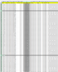
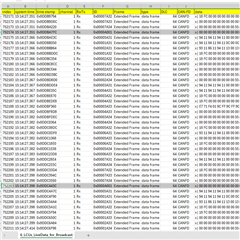
      (I had only 7 local nodes and a main node on the bus here in the data)

    It was working OK until there were 8 local nodes and the main node on the bus, I was observing all the frames, no data loss but the sequence (not important, just an observation) was jumbled. 1st frame from 5th local node- 5A31 was observed coming first over all the other nodes. and the rest of the frames the same 5th node came later in the bus (as seen in the picture from the .csv from CAN analyzer).

    The other observation I made regarding the timing was-- the main node broadcasts according to the number of local nodes. In the program, the main node broadcasts every 10 ms. If I had up to 2 local nodes on the bus, the main node was broadcasting every 10 ms as programmed (the broadcast function is in the 10ms timer function) ... but as soon as I put more local nodes on the bus, the main node started broadcasting in longer intervals:

    3 local nodes - main node broadcasts every 20 ms (even though the broadcast function is in the 10 ms timer)
    4 local nodes - every ~30 ms
    6 local nodes - every ~40 ms
    8 local nodes - every ~50 ms

    I wonder why this is happening. Maybe the intervals are being extended because the main node is waiting for the local nodes to finish transmitting? Maybe the bus is congested? I'm not sure.

    The last thing I want to mention is what's happening when I have 9 local nodes on the bus along with the main node. 


    I'm missing the last frame from the 9th local node (ID:9A34). At times, the frame comes right after the main node broadcasts (A001), at times, it shows that the frame is arriving after the main node broadcasts the next time (?). I was wondering what you thought about all this.

    I tried increasing the nominal bit rate from 500 Kbps (current) to 1 Mbps... I observed bus-off, warning status and error passive registers become 1 so I assume that was not the answer.

    I apologise for the large message, I understand if you need a little longer to go through all this and reply, thank you ever so much for your responses.

    Best,

    Nalin

  • Hi Nalin,

    Sorry for the delay in responding.  I'm clear now on how you implemented DAR.  Based on the other symptom you described during the reception of the acknowledge frame from local nodes wherein the data seems to be jumbled, are you using Tx Buffers to transmit the data to the main node? There is actually a known bug (errata) related to this:

    Workaround is to use Tx FIFO instead.  Maybe you can give this a shot if using Tx Buffer.

    Regards,

    Joseph

  • Hi Joseph,

    Not a problem, just to confirm... when I programmed the local nodes to produce an acknowledgement in response to the broadcast from the main node, I'm able to see all of the acknowledgements in the right sequence.

    Now because this scenario was OK, I graduated to program each local node to respond with 4 frames of 64 bytes each, i.e., 4 frames * 9 local nodes gives 36 frames... this was when the sequence started to get jumbled.

    Since then, I added a cascaded delay of 100 micro seconds (Local node number * 100 us) so that the first node responds with a delay of 100 us after the broadcast, the second one after 200 us and ... the 9th after 900 us, just to make sure the bus is not being tampered with a lot of frames being sent at once. This got the frames to come in a sequence without much of a delay.

    I was still losing the last frame from the 9th node, I assumed it was because the next broadcast was being too quick so I moved the broadcast function in the main control unit from a 10 ms timer task to a 20 ms one. Now, with 9 local nodes and the main node on the bus, broadcast comes every 60 ms. Could you answer why this is happening?

    My nominal bit rate is 500 Kbps and data bit rate is 5 Mbps and the requests and responses are still very slow (broadcasts per 60 ms, when it is scheduled for 20 ms)... how do I get my processes to run faster? Is there any configuration I'm missing?

    are you using Tx Buffers to transmit the data to the main node?

    I'm using the Tx FIFO itself.

    Best,

    Nalin

  • Hi Nalin,

    Thanks for providing more details.  Ok, so we eliminated the issue as TX buffer bug.  If I recall it correctly, when Disable Auto Retransmission is set (meaning frames that failed to transmit won't be retransmitted), main node is not getting most of the acknowledge frames or not getting any responses from other nodes at all but with DAR=0, repeated transmit attempts seem to be able to send the correct frames from all nodes.   This might be a symptom of signal quality issues on the CAN bus.  You probably already have the 120-ohm termination on the CAN bus and to check just to make sure that it is there.  This load would help prevent signal reflection that may affect signal quality.

    Would you be able to scope the CAN bus to inspect signal quality?  One channel for CAN_H and another channel for CAN_L and do a math operation (differential function) to represent the CAN data. Picoscope or any oscilloscope with a CAN-FD decoding function would be a great help for this.

    Best regards,

    Joseph

  • Hi Joseph,

    I have 120 Ohm resistors on all control cards in between CAN_H and CAN_L pins and I also checked for the equivalent resistance on the bus and it was 60 Ohms.

    I tried scoping the signal on the scope but it doesn't have a CAN-FD decoder per se, just says CAN and I couldn't figure out the signal much. I'll try it out again.

    I was wondering if there's anything I can do in the firmware to get the transmission faster, any configuration that I could look into, as well. Thanks for your response.

    Best,

    Nalin

  • Hi Nalin,

    Would still be valuable to examine the CAN bus waveforms to see if there are any signal disturbances happening that may cause parity errors, form errors...etc.  One symptom of this is the high number of errors observed from MCAN_ECR register and the errors reported in MCAN_PSR.

    One thing you can also try is to implement Transmitter Delay Compensation (see section 45.5.4 in TRM).  See the description and implementation in the TRM.

    Regards,

    Joseph

  • Hi Joseph,

    Sincerest apologies for responding this late, I have updates-

    I have verified the waveforms on a scope and there's a clear disturbance/noise on the signal even though the eq. resistance is confirmed to 60 Ohms and the length of the wiring is very short (~0.2m in total from all nodes combined).

    Transmitter Delay Compensation is already enabled but I found that all this time, I had bit rate switching disabled in MCAN initialization (MCAN_InitParams.brsEnable) but enabled in the Tx Buffer Element configuration (MCAN_TxBufElement.brs). This essentially meant that even though my bit rates were calculated in my code to be 500 Kbps Nominal and 5 Mbps Data, the transmissions were still running at 500 Kbps for both.

    I enabled Bit Rate Switching in both places but then, there was no transmission between 1 Master and 1 Slave node. I then assumed that 5 Mbps could be too fast so I calculated for 1 Mbps Data Bit Rate and then, later for 500 Kbps Data Bit Rate but was unable to observe any transmissions even then. 

    I checked this with the example code as well (mcan_config_c28x with mcan_ex2_external_loopback in CM). In the example, MCAN_TxBufElement.brs is disabled but MCAN_InitParams.brsEnable is enabled but for a message to be transmitted with a different bit rate as compared to its arbitration, BRS must be enabled in both places (as specified in Table 45-9 in Tx Handling section in SPRUII0F).

    This issue is very similar to this question on e2e... I'll ask a related question there since that question is unanswered.

    Best,

    Nalin

  • Hi Nalin,

    It would be good to address the bus noise issue first if this is the cause.  TDC may not be able to help if there is noise in the bus.  Maybe check for loose connections or cold solder joints between the CAN TX/RX pins, the transceiver and the physical CAN bus itself.

    Regards,

    Joseph

  • Hi Joseph,

    I apologise for the late reply. I checked everything in the physical layer... seemed OK.

    The issue that I've zeroed into is using a 25 MHz MCAN clock (125 MHz CM_CLK / 5) . To get a 5 Mbps bitrate from that, I had to make-do with a maximum sample point of 60%... I later changed the clock to 40 MHz (120 MHz CM_CLK / 3) from which I configured the sample point to 75% to get 5 Mbps. I now observe that the transmission and reception of data from the main node to 1 other local node on the bus is going well. 

    I still got to verify this with all 10 nodes (1 main, 9 local) on the bus. Any further queries, I'll post them on the other question I raised that you answered to (here). We can close this thread. Your inputs are much appreciated.

    Best regards,

    Nalin