Tool/software:
Dear TI Support Team,
I am currently working with the TMS320F28388S controller and facing a parity-related issue in the SCIB module.
Using the TI DriverLib API, I have configured the SCIB port with no parity using the following command:
SCI_setConfig(SCIB_BASE, DEVICE_LSPCLK_FREQ, 9600,
              (SCI_CONFIG_WLEN_8 | SCI_CONFIG_STOP_ONE | SCI_CONFIG_PAR_NONE));
This results in the SCICCR register being correctly set to 0x0007, as per the device datasheet, indicating 8-bit word length, one stop bit, and no parity.
However, during testing with the Modbus Poll application (configured with no parity), the MCU receives corrupted data. Interestingly, when I switch the Modbus Poll application to even parity, the MCU starts receiving the correct data — despite the MCU still being configured for no parity.
To verify this behavior, I cross-checked using another Modbus tool (ModScan) and captured the communication using a logic analyzer. The results were consistent across tools.
I’ve attached:
-
Snapshot of the
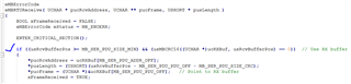
rx_buffershowing received data on the MCU side. -
Snapshot of the SCICCR register value.
-
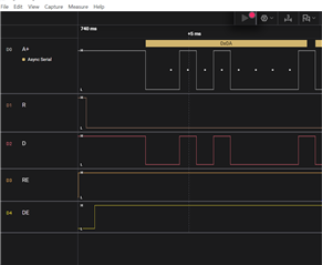
Logic analyzer waveform showing the actual data on the UART line.


This issue is blocking my Modbus communication setup, and I would appreciate your urgent support and guidance in resolving this discrepancy.
Please let me know if you need additional information.
Best regards,
Ramakrishna Panda