Part Number: TMS320F28P650DH
Tool/software:
Hello, expert. Currently, I am working on the communication of the F28P65 upper computer. The DSP is the SPI slave device, and the upper computer (made by QT) is the master device. Following the process of -spi_ex5_loopback_dma, I rewrote the code. When I debugged the upper computer, it was able to correctly send and receive 180 characters as shown in Figure 1. During the debugging process, the upper computer kept sending and receiving 270 characters, but it encountered an error as shown in Figure 2.
1.Question: If we only need to modify the SPI_DMA to send a fixed number of bytes and receive a fixed number of bytes, what code should be modified?
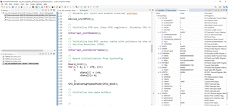
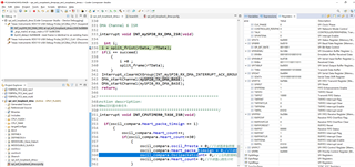
first
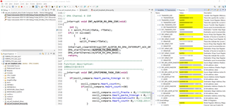
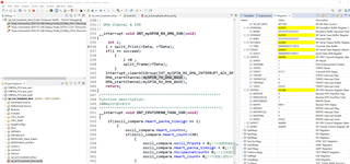
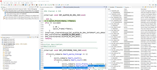
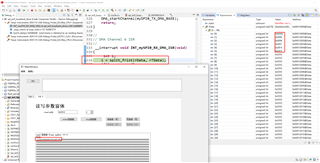
rData[] is the receiving array of SPI_DMA
Figure 1
------------This fixed byte is 180 characters long and the transmission and reception are both correct.
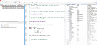
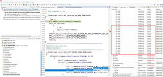
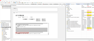
next
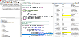
The upper computer sends data for the first time, and it enters the DSP receiving interrupt. The data is correct.
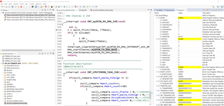
rData[] is the receiving array of SPI_DMA
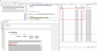
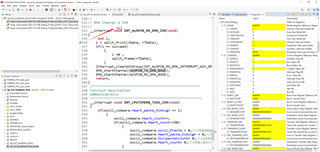
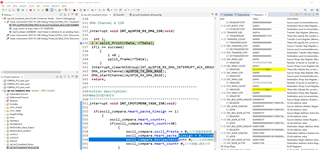
The upper computer sent the data for the second time, but it triggered the DSP's receiving interrupt. The data was incorrect.
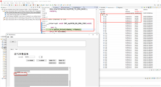
The upper computer sent the data for the third time, but it entered the DSP receiving interrupt but the data was incorrect.
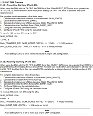
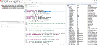
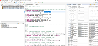
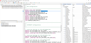
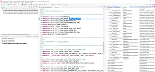
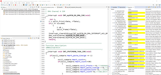
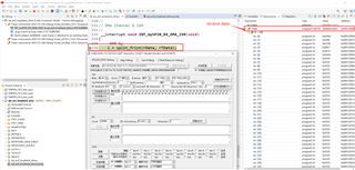
2.SPI configuration
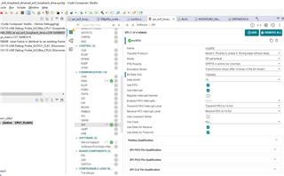
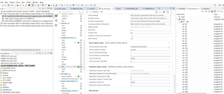
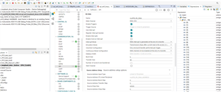
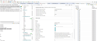
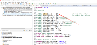
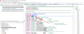
Figure 2
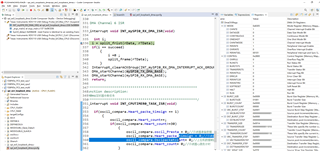
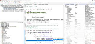
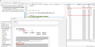
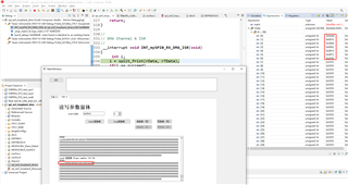
3.270-character fixed sending and receiving and 180-character fixed sending and receiving - modification points----The main task is to modify the TRANSFER and BURST data lengths, and also to adjust the lengths of the sending and receiving arrays.
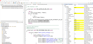
Question: If we only need to modify the SPI_DMA to send a fixed number of bytes and receive a fixed number of bytes, what code should be modified?
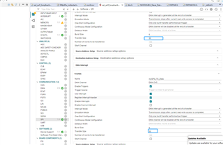
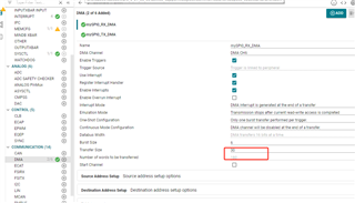
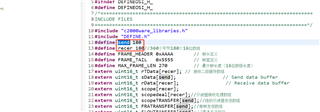
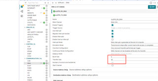
Figure3