This thread has been locked.

If you have a related question, please click the "Ask a related question" button in the top right corner. The newly created question will be automatically linked to this question.

TMS320F280039C: TMS320F280039 - Vector table allocation

Part Number: TMS320F280039C
Other Parts Discussed in Thread: C2000WARE

Tool/software:

Hi Ti team,

As we developed the Customized boot loader and application project in the TMS320F280039C

1. Customized boot loader code starting address - 0x0008 0000 - Flash Bank 0

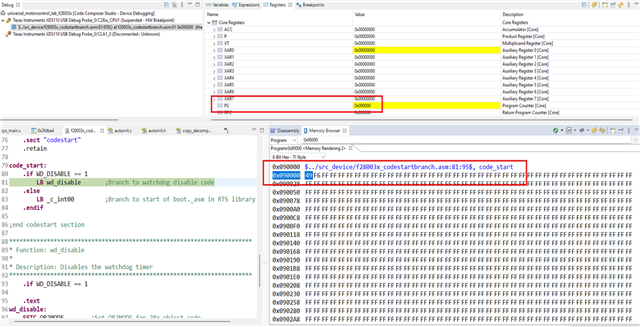
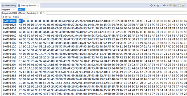
2. Application code(universal motor control) starting address - 0x0009 0000 - Flash Bank 1

3. For EEPROM data purpose we used 0x000a 1000 - Flash Bank 2 sector 1 location

Individual project was working fine. I used UDS protocol in the Customized boot project for flashing the application code.

Flashing process also working fine. After flashing i used to software reset function. After reset the CRC value verification process was done.
If memory write CRC value and calculated CRC value both are equal means i switch the program from the customized boot code into application project.

At that time i faced an error, illegal interrupt handler error.

Kindly suggest me to solve the above error.

I want to know the below queries,

1. Whether vector table separately have to create for both two projects?

2. How to allocate the location for interrupt vector table in flash memory?

3. How to reassign the flash memory location into ram memory location in run time?

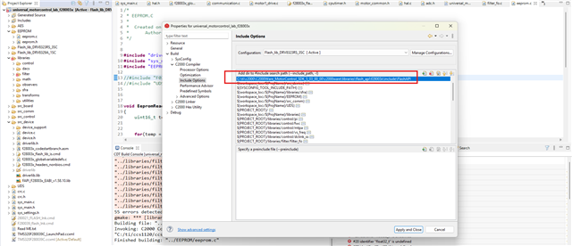
4. How to include the flash API library in the motor control project?

Advance thanks,

B.Punitha.

  • Hi,

    I'll be able to get to your question within the next day.

    Thanks and regards,

    Charles

  • Hi Charles,

               Awaiting for your reply.

    Thanks,

    B.Punitha

  • Hi Punitha,

    1, 2. Please consult the following thread solution for this issue: 

    TMS320F280049C: shift Interrupt vector table and jump to application - C2000 microcontrollers forum - C2000Tm︎ microcontrollers - TI E2E support forums

    3. For re-assigning Flash memory to RAM during runtime, you can look to the example provided in the F28003x Flash API linker command file:

     GROUP
       {
           .TI.ramfunc
           { -l FAPI_F28003x_EABI_v1.58.10.lib}
    
       }  LOAD = FLASH_BANK0_SEC1,
          RUN = RAMLS03,
          LOAD_START(RamfuncsLoadStart),
          LOAD_SIZE(RamfuncsLoadSize),
          LOAD_END(RamfuncsLoadEnd),
          RUN_START(RamfuncsRunStart),
          RUN_SIZE(RamfuncsRunSize),
          RUN_END(RamfuncsRunEnd),
          ALIGN(8)

    4. To include the Flash api library in the Motor Control project, you can check with the example provided by the flashapi_ex1_programming for this device in C2000ware and checking the Properties->C2000 Linker->File Search Path:

    The Flash API library for this device can be found here:

    C2000Ware_5_04_00_00\libraries\flash_api\f28003x\lib

    Thanks and regards,

    Charles

  • Dear Charles,

    1,2 - Already i follow the threat and implemented the steps, at that time the following error will occurred.

    and i removed the EALLOW portion , at that time while jumping from boot code into application code. The controller reset occurred.

    3,4 - I already followed the above steps in our code.

    In section mapping,

    Included the file search path,

    In the included option,


    After that also the below error occurred. I couldn't able to include the flash API

    Thanks, 

    B.Punitha.

  • For the PieVectTable inclusion, is the "device.h" header file included in this source file?

  • Yes. I included the device.h  header file in the source code.

  • Hi Punitha,

    Can you show where the initCanCOM function resides? Is it the function that is calling the 'run_app' function?

    For the PieVectTable, it's definition should reside in the device's globalvariabledefs.c file. Can you look to the f28003x LED Blinky example in the C2000Ware Device Support folder for how includes are considered for this file?

    Thanks and regards,

    Charles

  • Hi Charles,

     I have noticed the PieVectTable definition resides in the globalvariabledes.c  file only. But in the Code above the interrupt function the below lines available

    #pragma CODE_SECTION(canaISR, ".TI.ramfunc")

    In motor control project also below lines available

    #pragma CODE_SECTION(motor1CtrlISR, ".TI.ramfunc");
    #pragma INTERRUPT(motor1CtrlISR, {HP});

    And i noticed another point also, In map file the ISR routine available in flash memory. But the execution persists in RAM.

    Motor control map file

    Customized boot code

    In above two projects the ISR routine available in Flash memory but execution persists in RAM.

    While changing the control from customized boot code into application code, the code enter into reset function.

    Kindly suggest to resolve the issue, and to change the control from boot code into application code.

    Thanks and regards,

    B.Punitha.

  • Hi,

    Before configuring the Interrupt Vector Table, the interrupts must be cleared by the previous bootloader code application (as canaISR is present in both examples). Can you try disabling the interrupts before branching to the application?

    Thanks and regards,

    Charles 

  • Hi Charles, 

    Yes. I disabled all the interrupts before branching from boot code into application code.

    Below code is the implemented in our source code

    After implementing the above code, the following error occurred

    After executing the PC comes into boot code starting point.

    Kindly check whether the above process is OK or not.

    Thanks and regards,

    B.Punitha

  • Hi Punitha,

    Can you return out of the main application prior to branching to the next application? What entry address do you want to return to?

    Also, why does is the jump to cinit and not to codestart ?

    You can look to the examples present in the CAN Flash Programming of C2000 Microcontrollers application note for F28003x devices as a reference.

    Thanks and regards,

    Charles

  • Hi Charles,

                   I couldn't able to understand the above the application.

    My customized boot code project in the Flash Bank 0. Starting address = 0x80000

    Application code lies in the Flash Bank 1. Starting address = 0x90000

    I used to program the device through CAN  - UDS protocol using the Customized boot code.

    After programming, forced to device reset. Come out from reset the program check the CRC values and the process have to shift the application project, starting address 0x90000.

    In power on condition also the program starts from boot code and after CRC verification the project have to jump the application part.

    The above requirement i need.

    Kindly suggest the jumping process from Boot project to application project.

    Thanks and regards,

    B.Punitha.

  • Hi Punitha,

    Our expert is out of office this week so please expect some delay in response. In the meantime, could you refer to the flash_kernel_ex3_codestartbranch.asm file in the C2000Ware SDK (C2000Ware\driverlib\f28003x\examples\flash\flash_kernel_ex3_codestartbranch.asm)? Ideally, you would return your application's codestart address from the main function of your bootloader instead of jumping to it directly.

    Best,

    Alex

  • Hi Alex,

    Still i couldn't solve the issue. 

    Customised boot project details,

    1. Start address = 0x80000

    2. Stack = M1

    3. Interrupt used  = CAN interrupt

    4. RAM used = RAM LS 

    universal motor control application project details,

    1. Start address = 0x90000

    2. Stack = M0

    3. Interrupt used  = CAN interrupt, ADC interrupt for motor control

    4. RAM used = RAM GS

    The below queries i need to clarify related to jumping from one project  to another.

    1. How to change from one flash bank  to another flash bank in run time.
    2. Vector table and reset interrupt handling during changing one project to another project during runtime.
    3. How to edit codestartbranch.asm file in the project

    Can you explain in details.

    Thanks and regards,

    B.Punitha

  • Hi Punitha,

    Can you confirm that you have tried returning the entry point of your universal motor control application (0x90000) from the main function of your bootloader? Switching flash banks should not be an issue.

    codestartbranch.asm should be a file in your project that you can modify to look like flash_kernel_ex3_codestartbranch.asm.

    You might also want to have a look at Live Firmware Update with Device Reset on C2000 MCUs (Rev. A) for information about interrupt handling.

    Best,

    Alex

  • Hi Alex,

    Thanks for your reply.

          I included the below code in the bootloader main function, 

    APP_ENTRY_ADDRESS = 0x90000;

    While executing the above code initially the below  

    Working done. After some execution 

    Then controller enter into software reset, continue the same boot project only.

    In codestartbranch.asm file i didn't do any correction

    While i did the correction same as flash_kernel_ex3_codestartbranch.asm  at that the code was not working properly. 

    Exit:

    __stack: .usect ".stack",0
    MOV SP,#__stack
    MOV *SP++,#0
    MOV *SP++,#0
    PUSH ACC
    POP RPC
    ZAPA
    MOVL XT,ACC
    MOVZ AR0,AL
    MOVZ AR1,AL
    MOVZ AR2,AL
    MOVZ AR3,AL
    MOVZ AR4,AL
    MOVZ AR5,AL
    MOVZ AR6,AL
    MOVZ AR7,AL
    MOVW DP, #0
    MOV *SP++,#0
    MOV *SP++,#0x0A0B
    POP ST1
    POP ST0
    LRETR
    .end

    .end

    If i include the above correction in codestartbranch.asm file at that time CAN interrupt and boot loader project was not working.

    Thanks,

    B.Punitha

  • Hi Punitha,

    What are the contents of the Reset Cause register (RESC) found under CpuSysRegs when the application project resets?

    Additionally, after branching to the application are you able to determine what address and within what function the reset occurs at?

    You will need to load the symbols for the application project after branching.

    Thanks and regards,

    Charles

  • Hi Charles,

       What are the contents of the Reset Cause register (RESC) found under CpuSysRegs when the application project resets?            


    Watchdog reset occurred.

    Additionally, after branching to the application are you able to determine what address and within what function the reset occurs at?

     Initially the controller enter into 0x90000 address

    after press F5 controller enter into 0x90084


    At 0x3FEEF9 location the controller wait for some time. I think this was the In ITRAP ISR location

    After continuous running the device enter into boot code starting point of main.

    You will need to load the symbols for the application project after branching.

      May i know what symbols i have to load in the application projects.

    Thanks and regards,

    B.Punitha

  • Hi Punitha,

    Are you disabling watchdog in the motor control application? You would load the symbols for your motor control application after branching to it. This can be done by going to Load > Load symbols, then selecting your application .out file.

    Best,

    Alex

  • Hi Alex,

             Yes. I am disabling watchdog in motor control application. At that time also controller is not switching to application project. 

    Customised boot project itself i have to load the load symbols of .out file eh?

    Thanks and regards,

    B.Punitha

  • Hi Punitha,

    Yes, the process would be to run your bootloader project, branch to the application at 0x90000, then load the symbols for the application and step through it until you see a reset. Additionally, is the watchdog bit set at the time you branch to the application, before you observe the reset?

    Best,

    Alex

  • Hi Alex 

    While jumping into application project at that time PC loads 0x3FDBA4 location, after run the pc enter into 0x3FEEF8 location and ESTOP occurred.

    Need one clarification,

    Whether the boot table value affects this process?

    0xd00,0xd01 represent the boot table value

    0xd04 = holds the project starting address,

    In our Boot project , i loaded 0x03 = 0xd04 location as starting point at 0x80000.

    But our application project have to starting point as 0x63.

    Whether i load the 0x63 value into 0xd04 location before changing the application project?

    Thanks and regards,

    B.Punitha

  • Hi Punitha,

     Initially the controller enter into 0x90000 address

    While jumping into application project at that time PC loads 0x3FDBA4 location, after run the pc enter into 0x3FEEF8 location and ESTOP occurred.

    These seem like two different behaviors, does the PC ever go to 0x90000, or does it immediately go into ITRAP?

    Whether the boot table value affects this process?

    No, this shouldn't be a factor. Your device should be in flash boot mode and boot to address 0x80000 so that your bootloader starts at device power on. The bootloader will then jump to the application after your CRC check, i.e. it doesn't need to go back through boot rom.

    Can you confirm that your application is getting programmed correctly using the "Verify Only" functionality from the CCS On-Chip Flash Programming tool? Based on your earlier image of your assembly code, it looks like there may be a programming issue.

    Best,

    Alex

  • Hi Alex,

             Application code loaded using debugger tool at that time the images are,

    Application code loaded using CAN tool through our Customised boot loader code, at that time the images are


    Both the images are same. I think no difference in programming process.

    While jump into application project from Customised boot code, 

    Initially PC loads 0x90000 address


    After press f5 at that time PC loads 0x900F6 ADDRESS

    Press F5 ==> 0x3F00FF

    Press F5 ==>0x3FEEC9

    Press F5 ==> 0x3FEE8

    After Press F5 ==> PC returns into starting of main in Boot code.

    But while running the application code through the debugger at that time PC does not enter into Boot ROM portion.

    While jumping process i follow the below routine,

      asm(" LB *XAR7");

    }

    in above routine load address == 0x90000

    Kindly suggest to resolve the issue.

    Thanks and regards,

    B.Punitha


  • Punitha,

    Can you share a TI-TXT dump of your application?

    Best,

    Alex

  • Hi Alex,

               I fount one thing in programming process, i missed upper nibble of the each memory location. 

    That means for each address i write only lower 8 bits, i didn't write the upper 8 bits. So only my jump function is not properly work. 

    I am trying to write the both 16 bits value in each address location. Once i complete that then the jump function is working fine i think. 

    After complete i will inform..

    Thanks for your suggestions,

    B.Punitha.