This thread has been locked.

If you have a related question, please click the "Ask a related question" button in the top right corner. The newly created question will be automatically linked to this question.

TMS320F28P650DH: ALL IO down for 5ms

Part Number: TMS320F28P650DH


Tool/software:

Hi Experts,

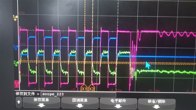
My customer is running power test and they observes strange behavior

It happens sometimes, that most IO would output low for 5 ms, and then restores normal operation.

They tested IO for PWM and several communication peripherals, and they all outputs low when the issue happens.

In the 5 ms duration, the device is not in reset. The ISR still runs normally as they observe the ISR counter. The background loop also runs normally.

It seems that in the 5 ms duration, all IO outputs low and other function of the device is not affected. 

This issue only happens with power stages, and it happens some time after power on.

Any idea what might cause this issue?

Regards,

Hang.

  • Hi Hang,

    Appologies for the delayed response. Can you provide more details into the power stages mentioned here? Is it possible to provide scopeshots or a timing diagram to demonstrate the power up sequence, ISR timings, and IO ouptuts in your test?

    You mentioned that it happens sometimes, how often is there any repeatibilty to the issue?

    Thank you for your time, the additional information  will help us continue to debug.

    Best Regards,

    Zackary Fleenor

  • Hi Fleenor,

    I am requesting customer to share power sequence and ISR timings. Though, how is this related to power sequence?

    Below is the picture of IOs.

    Blue is PWM, you can see it goes low.

    Read is RESET and yellow is the external oscillator. You can see them working normally.

    The condition to trigger the "dead" behavior is unclear, and it happens rarely. 

    Customer added a timer function in timer ISR to see if the CPU is running normally in the "dead" time. They captured case where the MCU is dead for 36 minutes, and revived when the probe touched one of the gnd of the secondary side of the LLC converter (which is the power stage). They read the timer after revival and it shows 9.7 minutes. This may indicate the CPU is working for some of the time when it's "dead"

    Below they capture more PWM outputs. One of the PWMs is stretched before it goes high. There are no intended PRD changes in this case. 

    is it possible that the clock is stopped for some moments? is there a way to check it?

    Regards,

    Hang

  • Hang,

    From the description I think we may be activating the boundary scan mode of the device through un-intentional noise on the JTAG pins.  Boundary scan will isolate the IOs from the device, but would not impact the CPU operation.

    This device uses 4 pin cJTAG; the most important pin to avoid activating the JTAG during operation is TMS.  We need to keep this signal high/3.3V when the debug probe is not connected.  The DS recommends 2.2kOhm PU, let's verify that customer has implemented this on their schematic, as well as confirming the resistor value on the PCB with a multi-meter.

    We could also scope TMS during the device operation to see if we observe coupled noise when the power stage comes on that may be activating this to a low.

    If PU is correct and populated, then as an experiment I would ask to tie TMS directly to VDDIO with a shunt, to see if this improves the occurrence.  JTAG will not work with the shunt in place, but just want to see if functionally this helps, and that would confirm this is the root cause.

    Best,

    Matthew

  • Hi Matthew,

    Seems that JTAG signals are indeed related to the issue. Customer connected the JTAG with a open-end wire the route the JTAG signal out of the shell. 

    Upon removing the open-end wire, they have not seen any occurrence of the issue up to now. They are running more test to confirm this.

    Regards,

    Hang.

  • Thanks Hang, keep us posted on the results.

    Best,

    Matthew

  • Hi Matthew,

    In one of the customer's cases, the issue is hard to reproduce. Therefore they can not be sure if the above method can solve the issue.

    Could you help providing more details on the consequece of TMS noise? like the mechanism of how TMS trigger this issue. They want to repduce the issue by injecting noise in TMS and see if they can get the same phenomenon to comfrim if this is the root cause. 

    Regards,

    Hang

  • Hi Hang,

    Both Matt and Zack are currently out of office so I'm looping in another expert to look at this. Please allow him 1-2 days to respond.

    Best Regards,

    Delaney

  • Hi Hang,

    TMS is used in the JTAG standard to advance the TAP Controller state machine as shown below:

    Technical Guide to JTAG - XJTAG Tutorial

    Noise on any of the JTAG signals should be accounted for correctly in hardware for good signal integrity. I found an excelent webpage describing common issues. Please refer to the Poor Signal Integrity section of the ilnk below.

    Common JTAG Connectivity Issues and How to Solve Them (A Designer’s Perspective)

    https://oxeltech.de/common-jtag-connectivity-issues-and-how-to-solve-them-a-designers-perspective/#:~:text=Poor%20Signal%20Integrity%20Issue

    A detailed description of the hardware design guidelines can be found at the link below:

    Emulation and Trace Headers Technical Reference Manual (Rev. I)

    Best Regards,

    Zackary Fleenor

  • Hi Fleenor,

    Thanks for the state machine plot, it's very helpful.

    Meanwhile, could you please share more on the behavior of the run test idle state? Or, in which state customer is likely to observe the above phenomenon?

    Regards,

    Hang.

  • Hang,

    Whenever is the device is not in Test logic reset, there is potential for a fault.

    There is not one state in which it is most common to see errors, rather specific sequences of states will cause the JTAG architecture on the MCU to intervene with the CPU operation.

    The only safe way to guarantee no disruption from the debug probe is to remain in Test logic reset state. For this reason, external pullup resistors are recommended on TMS, with values given in the datasheet. 

    Best Regards,

    Ben Collier

  • Hi Collier,

    Is the intervention only limited to CPU operation or it may affect IO as well?  Since there are errors observed on the IO, customer want to confirm the IO issue is related to JTAG interference.

    Regards,

    Hang

  • Hang,

    The CPU can modify the IO values, so yes.

    Best Regards,

    Ben Collier