This thread has been locked.

If you have a related question, please click the "Ask a related question" button in the top right corner. The newly created question will be automatically linked to this question.

TMS320F28379D: TMS320F28379D

Part Number: TMS320F28379D
Other Parts Discussed in Thread: C2000WARE, TMDSCNCD28379D

Tool/software:


Hi 
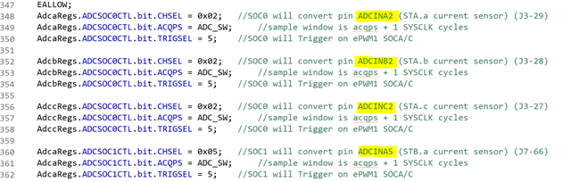
I previously inquired about this issue. The code is designed for the Launch XL, but I need to locate the corresponding pins on the F28379D control card and MCU docking station. If anyone has insights or knows the exact mapping of these pins on the control card and docking station, please let me know. I have reviewed all the pin combinations provided by C2000Ware, but those pins are not producing any signals. For example, for A2, it indicates pin 15 on the docking station, yet I am not receiving any signal on pin 15. Could someone assist me with this?

  • Hello Ubaid,

    To locate the correct pin mappings, check these directories:

    1- The Control Card documentation in:
    C:\ti\c2000\C2000Ware_5_04_00_00\boards\controlCARDs\TMDSCNCD28379D\

    2- The Docking Station documentation in:
    C:\ti\c2000\C2000Ware_5_04_00_00\boards\ExperimenterKits\DockingStation_HSEC_120or180pin\
    Make sure to select the appropriate revision for accurate pin mapping.

    Regarding ADC pins, these are inputs pins designed to read external voltage signals. if you mean, you're not seeing changes in ADC result registers, verify that ePWM1 SOC A triggering is properly configured (based on your snap shot).

    For troubleshooting, try configuring a GPIO pin to toggle and use an oscilloscope to verify signal integrity at the docking station pins. This approach will help you determine if the issue is with pin configuration, ADC setup, or physical connections.

    Best Regards,

    Masoud

  • Hi Masoud,
    I reviewed the documents, and it states that the pins for the ADC range from 13 to 46. However, I specifically want to confirm the pin for ADCINA2, B2, C2, A5. Based on my tracing, it indicates pin 15 on the docking station for A2. Yet, when I connected to pin 15, the oscilloscope displayed a flat line. Epwm is fine and was showing a signal. 

    Regards

  • Hello Ubaid,

    Yes, ADC pins are ranged from 13 to 46 in HSEC connector. And yes, ADCINA2 is routed to pin 15 on HSEC connector. But what do you expect to see when you connect the ADC pins to the oscilloscope? These are input pins and user are supposed to apply feedback signals to them. After that, you can read back the results in ADC register bits and confirm that ADC configured correctly.

    Best Regards, 

    Masoud 

  • Hi Masoud,
    Apologies for the delayed response. I’ve attached a picture of the oscilloscope showing the signals I’m observing when connecting the EPWM1 pin49 (yellow) and A2 pin15 (blue). This is the type of signal or noise I’m receiving. Could you help identify what might be going wrong or where the issue lies?


  • Hi Ubaid,

    As mentioned before, ADC pins are input pins and user are supposed to apply feedback signals to them. Based on what you're describing, you keep the ADC pins floating and monitoring ADC pin on scope. As a float pin it can get the noise from switching around. Again, to verify ADC signal integrity at the docking station, you should apply a ref voltage on docking station and reading back the value after conversion in the ADC result register.

    Best Regards,

    Masoud