Part Number: TMS320F28069M
Tool/software:
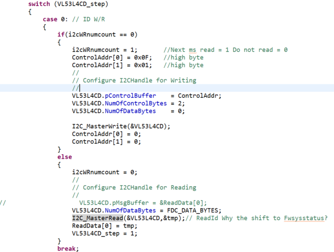
Here we use the instaspin solution to rotate the motor, and then add I2C communication to communicate with the VL53L4CD sensor. There is a problem with reading data displacement.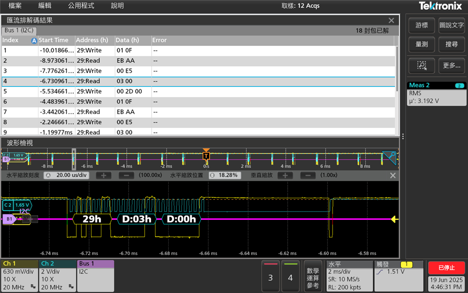
Follow the steps below to send and receive
step1. WRITE Addr: 0x29 ControlData: 01 0F
step2. READ Addr: 0x29 ControlData: EB AA
step3. WRITE Addr: 0x29 ControlData: 00 E5
step4. READ Addr: 0x29 ControlData: 03 00
step5. WRITE Addr: 0x29 ControlData: 00 2D 00
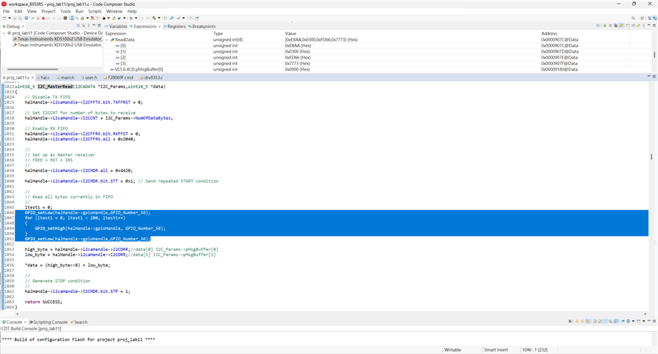
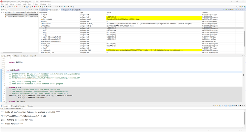
According to my program definition, the value of EB AA should be returned to ReadData[0], and the value of 03 00 should be returned to ReadData[1]
But the result is as follows
ReadData[0] = 03 00
ReadData[1] = EB AA
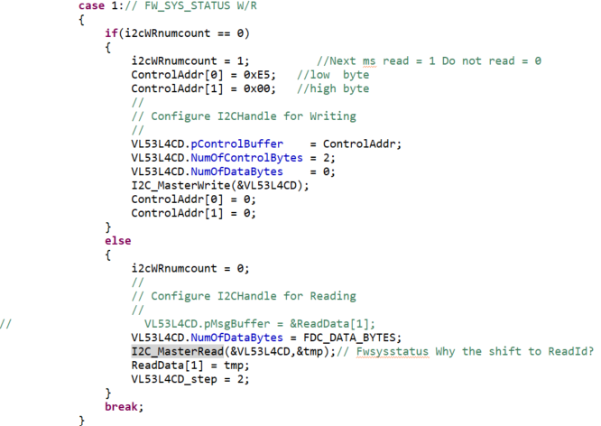

有什麼問題嗎?