Part Number: TMS320F28P650DK
Tool/software:
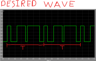
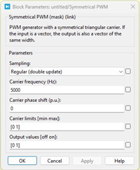
I have been trying to replicate the Symmetrical PWM block in PLECS, where specifically the carrier phase shift is set to 0.
The DSP in this case is the TMS320F28P650DK (same happens in the F28379D).
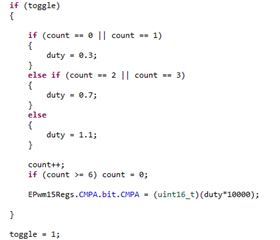
The following code is written in the ADC ISR that triggers the interrupt every top and bottom of the triangular carrier, set to 5kHz (which means 10kHz interrupt frequency), which translates to TBPRD = 10000.
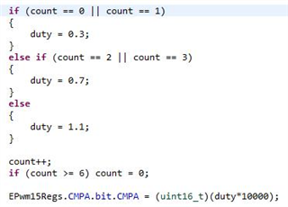
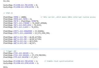
The pwm configuration is set to pwm 15, where the configuration is given below:

Now here's the problem: The ePWM block only matches PLECS' symmetrical PWM block when the sector "carrier phase shift" is set to 0.5 (180 degrees phase shift of the carrier).
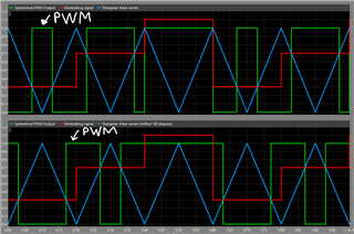
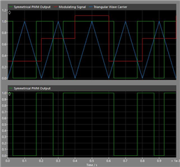
As a means to illustrate that, here are the pictures out of PLECS' symmetrical PWM block when "carrier phase shift" is set to 0 (carrier starts from the top):

where the line in red is the modulating signal, which is exactly the same value read in the CMPA register:
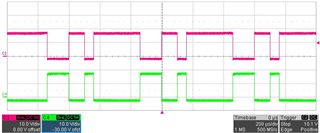
Now, for the "carrier phase shift" PLECS' block set to 0.5 (carrier starts from the bottom):
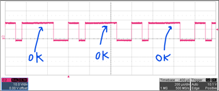
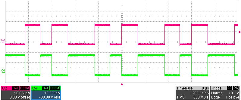
In this case, the figure above matches what is seen on the scope in red (or pink. Green is the complementary signal):
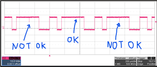
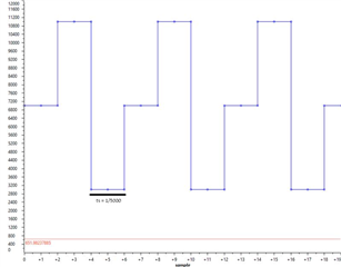
To try to counter that, I set up a variable to "miss" the first half cycle of the carrier (a simple if condition to by pass the code in the very first ISR trigger), this way "shifting" the code 180 degrees.. to no avail as it can be seen in the next figure:
I also tried setting TBCTR to start at the same value as TBPRD to force the carrier to start from the top as shown in PLECS, but it also does not work.
Conclusion - What is wrong with I'm doing there? It's a very simple routine and I'm not sure how to set that PWM to replicate the same behavior in PLECS when the "carrier phase shift" is set to 0.
Any help would be much appreciated.