This thread has been locked.

If you have a related question, please click the "Ask a related question" button in the top right corner. The newly created question will be automatically linked to this question.

BOOSTXL-BUCKCONV: Second PWM pulse inside same switching cycle - Peak current mode of control

Part Number: BOOSTXL-BUCKCONV
Other Parts Discussed in Thread: SFRA, TIDM-DC-DC-BUCK, OPA354, INA240, OPA353

Tool/software:

Hello TI support Team,

I am working on PCMC of my boost converter using provided example of TI-BOOST-BUCKCONV. I change the dacrefpu to 0.2 and everything looks fine. 

When TBPRD = 0 then EPWM8A generates on pulse and on reaching iL_amps_pu  = DAC reference (0.2) then EPWM8A turns off and I see good waveforms with respect to iL on scope.

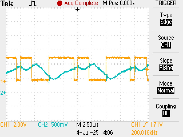
Problem arises when the dacrefpu is > 0.3. I see a second turn on pulse just after turn off of the comparison event in the same switching cycle. It can be seen from below.

I see that after removing the EPWM8A on pulse there is some spike on the inductor current iL. But a next switch on pulse should be generated only only when TBPRD = 0. It looks like the second pulse we see on scope happens because of this spike on iL which it should not be happening

Please suggest me how can I fix this.

With Regards

Nagella

  • Hi Nagella,

    Can you provide the scope waveform for the inductor current when dacrefpu is set to 0.2 so I can compare?

    I'm wondering on your custom board, do you have any filtering on the current sense input which is causing some delay in the reading of the current from the MCU side? The current should be falling during the off-time as you mentioned. And I can see there is quite a large delay from when the beginning of your EPWM cycle (when TBPRD = 0) until the inductor current starts to rise

    Since it looks like you have altered the pinmuxing from the original reference design, can you double check that the signal path from CMPSS to EPWMXBAR to EPWM is all correctly configured for your hardware?

    Regards,

    Peter

  • Hello Peter,

    Thank you for responding. Attached is the waveform of iL high side when dacrefpu is at 0.2. There is for sure delay betwen ewpm rise and iL rise and I dont know how to fix it as it is hardware related. There is no input filter but 0R resistance in path of IN+/- and there is output RC filter with 150R and 220pF for required bandwidth.

    The issue got fixed when I increased the RAMPDECVAL of the ramp generator from 7 to 26, which make slope steeper. But the delay is another issue I need to fix. INA240A2 is my sense amplifier with R002 sense resistor

    O: Before Output filter B: After filter iL_HIGH_SIDE

    O: EWPM8A, B: after filter iL_HIGH_SIDE

    With regards

    Nagella

  • Hi Nagella, 

    This waveform looks more appropriate for PCMC. For your boost converter, would you be able to provide a snippet of your schematic related to this circuitry? That would help to better understand what may be causing this delay

    Regards,

    Peter

  • Hello Peter,

    Sorry for the delay. Here is the schematic with high side current sensing.0 and a post filter connecting to uC adc pin.

    I have another query, when I am implementing peak current controlled current controller, do I need high bandwidth current sensing on the output while working with SFRA frequency analyser or is it okay to use low bandwidth controller INA186A3 on the output current measurement.

  • Hi Mohan,

    Thank you for schematic, a colleague and I will review this to better understand the design

    Regards,

    Peter

  • sure will be waiting

  • I see datasheet INA186A3 have very low bandwidth. General right thumb rule is to use sensor BW 10x of switching frequency in this case.

    Also, since we are using the inductor current signal directly as input to comparator and not providing to ADC, we don't need aggressive filters which smoothens inductor current shapes. So reduce your filter values to retain the shape of inductor current waveform.

    Also, following waveform shows sub-harmonic oscillation, a common phenomenon whenever effective duty of converter > 0.5. That is why we add ramp to the current reference (implemented by dac) provided to inner current loop. You can try increasing slope of this dac reference.

    Could you please provide us specification of your hardware?

    Regards,

    Sumit

  • Hello Sumit,

    Thank you for the response. I am using INA240A2 for inductor current sensing and I have waveforms represent the inductor current with respect to PWM pulse to low side mosfet.

    And I reduced the filter and there is no change in this offset of inductor current not starting from pwm pulse.

  • Considering 200kHz frequency, I fear that this INA240A2 still won't work. I see its BW as below which shows how op amp will response to sinusoidal signal. The signal that you are trying to amplify is triangular which contains multiple sinusoidal frequencies which are integer multiple of your switching frequency. Considering right thumb rule you need to have at least 2MHz+ BW OPAMP (10x 200kZ) for this application. We have used 44MHz OPAMP in TIDM-DC-DC-BUCK.

    Also, you are measuring floating differential voltage since current shunt is in series with inductor. Its CMRR may be good enough for motor application but not for high frequency buck converter. You can see where your switching frequency sits in this graph to see how much common mode voltage will get rejected.

    Also, I see from your post that with slope increasing you have fixed the issue when increasing slope where lower slope may cause subharmonic oscillation.

    I hope this helps. Let us know if any specific issue you are encountering after fixing items above.

    Regards,

    Sumit

  • Hello Sumit,

    Thank you for clarification. I got better idea on what specifications I need to pay attention to. I initially took OPA354 with 250MHz Gain BW but I saw the PWM switching harmonics in my sampled inductor current. So I went to INA240 with PWM rejection feature to have clean current sensing which I believe it is working well. But there is an offset which you mentioned as low bandwidth. If I go back to op amp then I amd afraid that I will see the pwm switching spikes on the current sense. I havent tried OPOA353 with 44Mhz bandwidth. If you suggest it can give clean current sense then I will try this out first.

    CMRR looks nearly same with my choices around 80dB with OPA354(250Mhz BW) and INA240A2 (400kHz BW) with being less on OPA353 (44Mhz BW) i.e 60dB which is being used on BUCKCONV design.

  • Mohan,

    It is not good idea to reduce the OPAMP bandwidth to get rid of current spikes. You can use R-C filter to reduce those sharp spikes. We have blanking window feature demonstrated in the code to mask those abnormal spikes during switching event and to avoid spurious cycle trips. You can enable or edit that. Also, please try using different slope values to see if your that resolves sub-harmonic oscillation.

    Kindly try these proposed method and let us know how it goes.  

    Regards,

    Sumit

  • Okay Sumit,

    Will do so and try out the op amps and will update the thread with new results

  • Okay, Let us know.

    Thank,

    Sumit

  • Hello Sumit,

    I see there is no suitable op amp in differential op amp configuration which can provide me 3.3V output i.e Vcm (18V) > Vs (3.3V) to feed the current sensing into 3.3V ADC pins of F280049C.

    So I guess I have no option other than choosing current sense amplifier where VCM > Vs right ?

  • Mohan,

    I am attaching the example for the the INA you may want to refer for the specs that you need for this design: https://www.ti.com/lit/ds/symlink/ina296a.pdf

    In this although supply is 3.3V its VCM is still −5V to 110V. The term you may want to use when searching for part is "wide common mode voltage range".

    Does that makes sense?

    Regards,

    Sumit

  • Sure,

    Ordered the parts and would be trying out soon. 

  • Sure, let us know if that resolved the issue.

    Regards,
    Sumit