


Part Number: TMS320F28377D
Tool/software:
Hi Expert
Customer use our F28377 in the power distribution unit they see some issues with ADC sampling as the picture shown below:
the blue line / white line/ yellow line are the incorrect ADC sampling output, when the power board powered up.
You can see the drop and rise of those 3 lines are the same, it means the same interfere signal may coupled to to 3 channels.
the green / red/ purple lines do not couples the interfere.

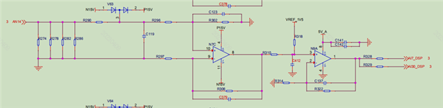
the hardware connection are below:
blue line - AI13(x0.58)-ADCIND2 / white line - AI7(x0.14) - ADCINB4 / yellow line - AI10(x1.4) - ADCINC2 , typical input circuit:
MCU schematic:

Do you have any suggestions to debug this issue?
Thanks
Joe
