This thread has been locked.

If you have a related question, please click the "Ask a related question" button in the top right corner. The newly created question will be automatically linked to this question.

TMS320F2800137: Add special deadtime to EPWMA and EPWMB

Part Number: TMS320F2800137
Other Parts Discussed in Thread: C2000WARE

Tool/software:

Hi,

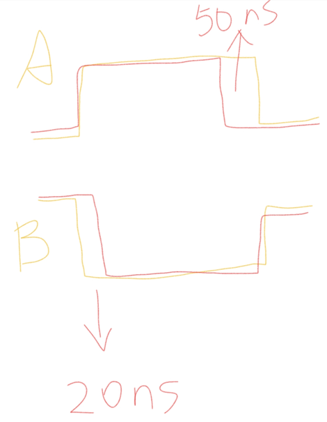
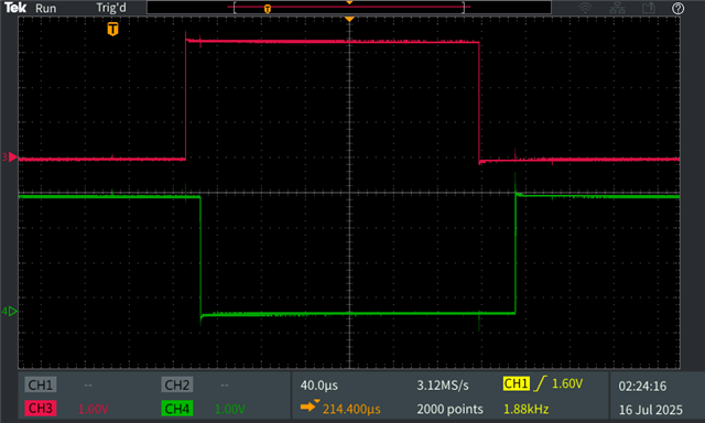
I want to add a special deadtime logic to my EPWMA and EPWMB channel.

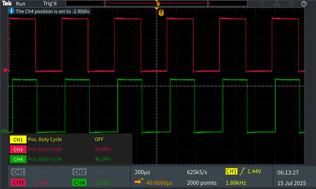
EPWMA has 50ns falling edge delay. And EPWMB has 20ns falling edge delay to compensate some propagation delay in the system.

Orange color is the original signal; red color is the modified signal.

Thanks!

Bowen

  • Hello Bowen,

    You can refer to the "epwm_ex8_deadband" example project for this logic. Please download C2000Ware and install it.

    Once installed you can import example "epwm_ex8_deadband" project in CCS from path "C:\ti\c2000\C2000Ware_5_xx_xx_xx\driverlib\f280013x\examples\epwm\CCS"

    Open the "epwm_ex8_deadband.syscfg" file to see the setting and modification that need to be done for this application.

    1. Select myEPWM4 which is configured with active high complimentary.

    2.  Since, TBPRD is "2000" in EPWM Time Base section, change the the CMPA and CMPB to "1000" for 50% duty for the simplicity for verification. 

    3. Now expand "Common Dead-Band Modes" from ePWM Dead-Band Section. Click on "SETUP THE DEAD-BAND MODULE" with Dual Edge Delay Mode as shown below. I have select value 250 and 100 by scaling your dead band adjustment by factor of 5 for experiment. You can calculate and adjust the count as per your requirement. 

    Following waveform for your reference where Red is ePWM4A and Green is ePWM4B

    Regards,

    Sumit

  • Hi Sumit,

    Thanks for your reply.

    But why the EPWM4A and EPWM4B is in same phase? I mean they should be complementary in most of the time.

    Also, do you have more information on the Dual Edge Delay Mode which shows how it works?

    BR,

    Bowen

  • 1. For complimentary switching, it can be changed in action qualifier. Please see following settings to make it complimentary.

    a.  Set action qualifier for A to be opposite of B as shown below to have complimentary switching.

    b. Then adjust the dead band value as shown below to add that complimentary phase shift value (180deg or 1000 count) on the top of original 100 count in FED. RED = 250 will remain the same.

    2. For Dual Edge Delay Mode please find the signal path settings needed from dead band module as follows. Unfortunately so far there is no app note for this specific use but TRM dead-band module explains function of each switching shown in this diagram.

    Please see updated PWM waveform for your reference where Red is ePWM4A and Green is ePWM4B

    Let me know if any question on this one.

    Regards,

    Sumit

  • Hi Sumit,

    Thanks a lot for your explaination!

    BR,

    Bowen