This thread has been locked.

If you have a related question, please click the "Ask a related question" button in the top right corner. The newly created question will be automatically linked to this question.

TMS320F28377S: Abnormal driver waveform

Part Number: TMS320F28377S


Tool/software:

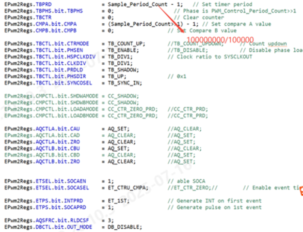
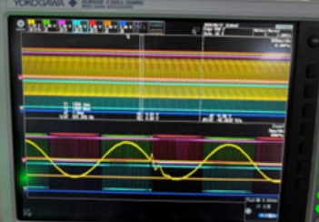
In the NPC three-level topology, when discharging and the positive half-cycle is cut from the negative half-cycle, one tube shows an abnormal pulse width, with a pulse width duration of approximately 400 microseconds. Before the positive half-cycle of discharge switches to the negative half-cycle, the current direction is outward. When tube 1 reaches its full duty cycle, the current rises, and the slope of the current increase is very large. The three-phase drives of A, B and C respectively use EPWM1, EPWM3 and EPWM5, and the three configurations are the same. Sampling is triggered by EPWM2. The configuration methods of EPWM1 and EPWM2 are shown in the figure. control.cla is triggered by EPWM11 with an interrupt frequency of 10k. The synchronization mode of EPWM1,3, and 5 is external input signal synchronization, and the synchronization signal is triggered once every 6ms. 1-channel - A-phase inductor current 2-channel -A phase 1-tube driver, 3-channel -A phase 2-tube driver, 4-channel -A phase 3-tube driver, 5-channel -A phase 5-tube driver. Could you please check if there is any problem with the timing of this configuration method that causes abnormal wave generation

  • Hi Hui,

    I've connected you to one of our ePWM experts to further assist. If you are using a reference design, could you confirm which one as well?

    Best Regards,

    Aishwarya

  • Hello,

    To identify potential issues with the timing of this configuration method, I'll highlight a few possible concerns:

    -Synchronization mismatch: The synchronization signal might not be aligned with the switching frequency of the NPC topology. This could cause timing mismatches and lead to abnormal wave generation.
    EPWM2 sampling timing: The sampling timing triggered by EPWM2 might not be optimized for the NPC topology, potentially causing inaccurate current measurements and affecting the control algorithm.
    Interrupt frequency: The interrupt frequency of 10k for control.cla (EPWM11) might be too high or too low for the specific application, leading to timing issues or insufficient control updates.
    Current slope: The very large slope of the current increase when tube 1 reaches its full duty cycle could indicate a lack of damping or inadequate control of the current, potentially causing instability and abnormal wave generation.