Part Number: TMS320F280049C
Other Parts Discussed in Thread: BOOSTXL-BUCKCONV, SFRA
Tool/software:
Hello TI,
I am working on a project with digitally controlled boost converter customized from BOOSTXL-BUCKCONV example.
My my task is to charge a 24V battery with 2A during CC mode and later on switch to CV mode with 28V output setpoint. My input is 12V, 250W max.
I worked on compensator design and extracted PID parameters both during CC and CV mode of operation on Boost converter. These entire design process was carried out on a resistive load of 6.6Ohm
Now comes the main part. Initially I started with following test setup to test CC mode of operation of my digital controller
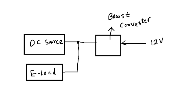
Output PSU @22V, 0.5A (to simulate battery being connected to my converter output ) connected to EL with CV mode setup @23V, 5A (to sink power delivered from converter output) ---> mock battery setup on output
Input PSU @12V, 250W
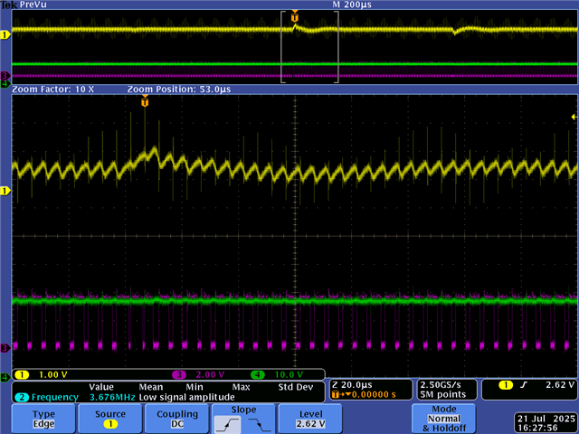
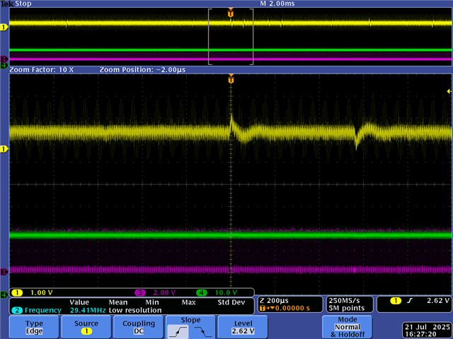
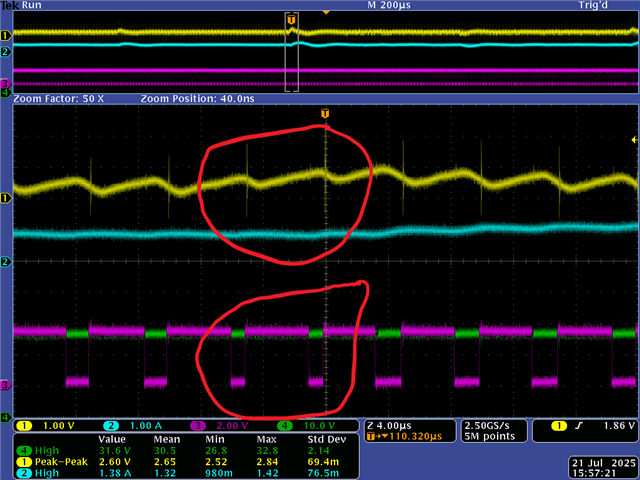
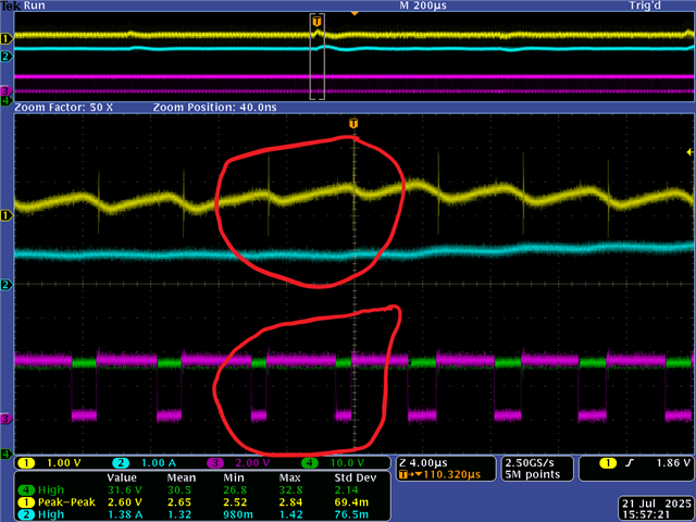
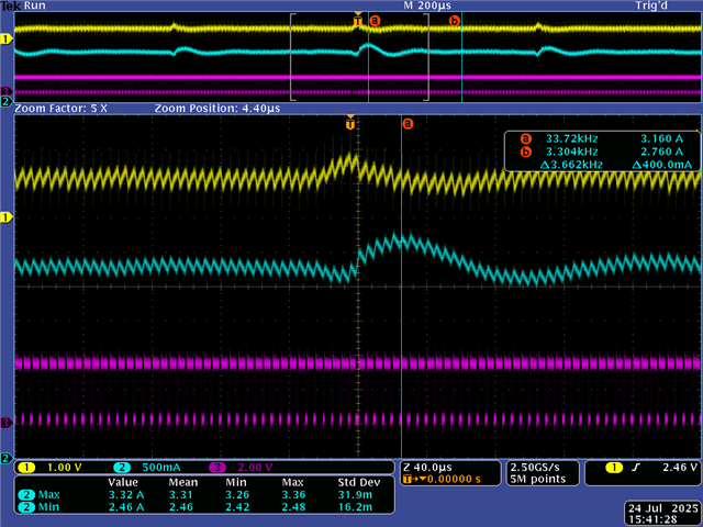
Problem: When I start with current regulation of 0.2A, the output voltage spikes and my inductor current trip protection is triggered thereby switching off my entire converter.
What I am doing wrong? My CC regulation works on resistive load but on above mock battery setup?
Do I need to first do CV regulation and bring my converter output to slightly above 23V so that current flows to the output and then switch to CC mode for regulating current ?