This thread has been locked.

If you have a related question, please click the "Ask a related question" button in the top right corner. The newly created question will be automatically linked to this question.

F29H85X-SOM-EVM: Which MCAN IOs working on HSEC180ADAPEVM?

Part Number: F29H85X-SOM-EVM
Other Parts Discussed in Thread: HSEC180ADAPEVM, SYSCONFIG

Tool/software:

Hello Experts, 

I am porting my old project from C28 to C29, and currently I am trying to use MCAN which is the same module, as per Migration Guide. 

I would like to inquire about...

1. Could you please advise me as to which IOs and MCAN module are available on the EVM and thus the HSEC180ADAPEVM board? I am somewhat confiused. According to the pinout, the connections are labelled MCANA, MCAND and MCANE. I am unable to send or receive anything from the MCAN modules, as demonstrated by the example. It is possible that I am not approaching this correctly.


Kindly find attached the example files, I have updated example 4, rest is mostly same, just configured with MCANE.   

 MCAN.zip

  • Hi Deep,

    Could you please advise me as to which IOs and MCAN module are available on the EVM and thus the HSEC180ADAPEVM board?

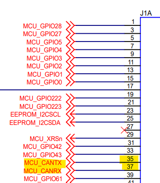
    By default, the MCAND (GPIO67 and GPIO68) are routed to J1 (Pin 35 and 37) of the EVM board. You can modify the EVM board to route MCANA (GPIO64 and GPIO65) to J1 header (Pin 35 and 37) instead. 


    Did you wire a CAN transceiver to the DOCK card? 

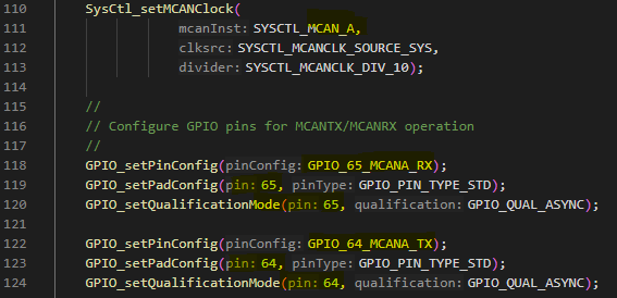
  • The mcan_ex4_transmit in f29h85x-sdk_1_01_00_00 release is a clone of MCAN example used in F28x device. You need to reconfigure the pinmux for MCAN. My suggestion is to use the sysconfig to generate the config file.

  • Yess. I have a transreceiver to the Rx Tx pins on the Dock. And I was unable to see any data transmission to the Transreceiver.

    I dont want to modify, I want to test the MCAN communication. I can use MCAN D module, if it is by defualt connected to the MCAN Rx Tx on HSEC180ADAPEVM at GPIO 68 and GPIO 67 respectively. But at which IO pins?  80 and 82?

  • My issue is not also about GPIOs, my real issue is, which GPIOs are connected to the HSEC180ADAPEVM and at which Pins?

    Earlier we use to get the Pin numbers here in the PinMux as well. It is so confusing right now. Like here, What does B15 and B16 in GPIO68/B15 and GPIO67/B16 stands for? 

    Also, when I am emulating the device, with 

    SysCtl_emulateDevice(SYSCTL_EMULATE_F29H850DM7);

    does any of it changes? 

  • What does B15 and B16 in GPIO68/B15 and GPIO67/B16 stands for? 

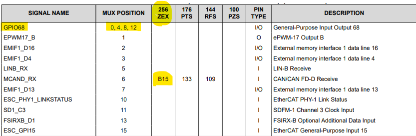
    B15 and B16 are the pin names of 256 ZEX (BGA) package. GPIO67 and GPIO68 are the default signal names mapped to pin B15 and B16. B15 and B16 can be used for several signals.

             For example, B15 can be used for GPIO68, or EPWM17_B, or EMIF1_D16, EMIF1_D4, ... etc which is selected by mux position (pinmux in sysconfig).


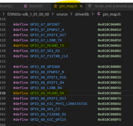
    To configure the GPIO pins for MCANDTX and MCANDRX:

        GPIO_setPinConfig(GPIO_68_MCAND_RX);
        GPIO_setPadConfig(68, GPIO_PIN_TYPE_STD);
        GPIO_setQualificationMode(68, GPIO_QUAL_ASYNC);
        GPIO_setPinConfig(GPIO_67_MCAND_TX);
        GPIO_setPadConfig(67, GPIO_PIN_TYPE_STD);
        GPIO_setQualificationMode(67, GPIO_QUAL_ASYNC);

  • which GPIOs are connected to the HSEC180ADAPEVM and at which Pins?

    GPIO67 and GPIO68 are connected to pin 82 and pin 80 of 180pin-HSEC header on HSEC180ADAPEVM.

  • My statement "The mcan_ex4_transmit in f29h85x-sdk_1_01_00_00 release is a clone of MCAN example used in F28x device" is not correct. This example in SDK 1.01 has been updated.

    You can use this example as a reference, and modify the code for MCAND.