This thread has been locked.

If you have a related question, please click the "Ask a related question" button in the top right corner. The newly created question will be automatically linked to this question.

TMS320F28379D: CCS

Part Number: TMS320F28379D

Tool/software:

Hi all,

I am working with two TMS320F28379D DSPs (DSP1 and DSP2) communicating over the CANB channel, and I'm facing an issue where data transmission from DSP2 to DSP1 is not received, while the reverse direction (DSP1 to DSP2) works perfectly.

My questions is  :"Why would DSP1 fail to receive data from DSP2, even though the reverse works?" . Please suggest how to resolve this issue. For your reference, screenshots are attached  herewith.

Thanks and best regards,

Sameer

CAN Transmission.pptx

  • Hi Sameer,

    What is the CAN error status on DSP2 side? Is the auto re-transmission enabled?

  • Hi,

    1. What the value are assigned to sys_mode_int.u8[0], and sys_mode_int.u8[1]? 

    2. There are only 2 bytes of data to be transmitted (txMsgData[1:0]), but the MSG_DATA_LENGTH=8 in your code. What is the DLC programmed to IFxCTL register? If the DLC doesn't match MSG_DATA_LENGTH, the message may not be transmitted.

  • Hi Wang,

    Thanks for your prompt response. 

    1.What is the CAN error status on DSP2 side?

    The last error status is 111.

    2. Is the auto re-transmission enabled?

    Yes. The automatic retransmission is enabled.

    3. What the value are assigned to sys_mode_int.u8[0], and sys_mode_int.u8[1]?
    sys_mode_int is a union containing a 16-bit variable and an array of two 8-bit variables.
    In this union, sys_mode_int.u8[0] stores the lower 8 bits (LSB) and sys_mode_int.u8[1] stores the upper 8 bits (MSB).
    The variable sys_mode has a value of 200, which is first stored as a 16-bit value and then split into its LSB and MSB components

    4. There are only 2 bytes of data to be transmitted (txMsgData[1:0]), but the MSG_DATA_LENGTH=8 in your code. What is the DLC programmed to IFxCTL register? If the DLC doesn't match MSG_DATA_LENGTH, the message may not be transmitted

    DLC is 1000 which is same as MSG_DATA_LENGTH(8).

    Screenshots are attached for your reference.

    Thanks and best regards,

    Sameer
    CAN Transmission-1.pptx

  • Thank you. 

    The TxOK in the screenshot is 0 which means that no message has been successfully transmitted since last time when this bit is read by the CPU.

    Have you measured the signal waveform on CAN bus when DSP2 is transmitting message to DSP1? Any CAN controller may start a transmission when it has detected an idle bus. This may result in two controllers on DSP1 and DSP2 starting a message (almost) at the same time. Since the bus is wired-and and a Dominant bit is logically 0, it follows that the message with the numerically lowest Arbitration Field will win the arbitration. The MSG ID on DSP1 is 0x1 (0x2 on DSP2), so the MSG on DSP1 will be transmitted.

  • Hi Wang,

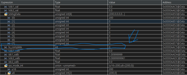
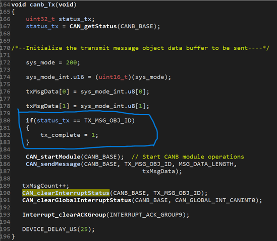
    Thank you for clarifying the fundamentals. In the transmitting code on DSP2, I am using a variable (tx_complete) to monitor the transmission status, but it remains at zero. This seems to indicate that the transmission is not completing. Please correct me if I am wrong. I have attached screenshots for your reference.

    Thanks and best regards,

    Mohammad Sameer Irfan

  • This seems to indicate that the transmission is not completing.

    From your code, you are correct, the transmission is not completed. Is the errorFlag set? 

    Can you comment out the code (highlighted below) in your canbSIR() since reading LEC will reset this field to 0x7?

    You can add a breakpoint in canbISR() to make sure there is interrupt happened. Thanks


  • Hi Wang,

    Thank you for your assistance — the issue is now resolved. However, I would like to clarify one point.

    Initially, for DSP1, I was using a project template that combined both register-based and DriverLib-based code, whereas DSP2 was implemented using only DriverLib-based code. In this setup, the CAN receive ISR in DSP1 was invoked through register-based code, while in DSP2 it was triggered via a DriverLib function. Under these conditions, DSP2 was able to receive data from DSP1, but DSP1 was not receiving any data from DSP2.

    Subsequently, I modified the setup so that both DSP1 and DSP2 used the same mixed approach (register-based and DriverLib). I then observed that in DSP1, the CAN receive ISR was still not being called. However, once I used a DriverLib function to register the ISR, it began executing correctly.

    Could you please explain why this difference in behavior occurs?

    Screenshots are attached for your reference.

    Thanks and best regards,

    Sameer

  • Do you mean that enabling the register-based code (no changes to other code) in your screenshot make the canbISR() stop working?

  • Yes, enabling the register based code and disable the driverlib ones(as in the following screenshot), the canbISR() stops working.

    Thanks and best regards,

    Sameer

  • Hi,

    The interrupt is not enabled in your register-based code. The __enble_interrupt() which is an compiler intrinsic function is to enable all interrupts.