Part Number: TMS320F28378S
Other Parts Discussed in Thread: C2000WARE,
Tool/software:
Hello TI team,
I am using example program i2c_ex6_eeprom_interrupt for for interfacing with RTC MCP7904.
C:\ti\c2000\C2000Ware_6_00_00_00\driverlib\f2837xs\examples\cpu1\i2c
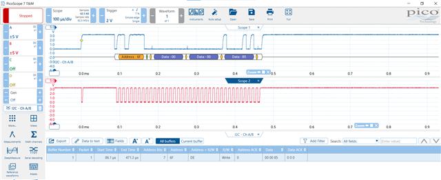
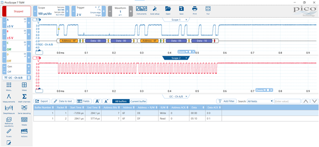
When i am writing first byte to RTC then 7th bit of first byte causing problem Other bytes read and write operations are correctly working.
For hardware circuit testing, if same byte i write through Arduino board then it is working fine means something wrong in programming side for TI TMS320F28378S not RTC hardware interfacing circuit.
I need help of TI team for what can be cause of this wrong operations or any library update required for I2C. Program is given below.
//
// Included Files
//
#include "driverlib.h"
#include "device.h"
#include "i2cLib_FIFO_master_interrupt.h"
//
// Defines
//
#define EEPROM_SLAVE_ADDRESS 0x6F
//! --------------------------------
//! Signal | I2CA | EEPROM
//! --------------------------------
//! SCL | GPIO105 | SCL
//! SDA | GPIO104 | SDA
//! --------------------------------
//
// Globals
//
struct I2CHandle EEPROM;
struct I2CHandle TempSensor;
struct I2CHandle *currentResponderPtr; // Used in interrupt
uint16_t passCount = 0;
uint16_t failCount = 0;
uint16_t AvailableI2C_slaves[20];
uint16_t TX_MsgBuffer[MAX_BUFFER_SIZE];
uint16_t RX_MsgBuffer[MAX_BUFFER_SIZE];
uint32_t ControlAddr;
uint16_t status=0;
//
// Function Prototypes
//
interrupt void i2cFIFO_isr(void);
interrupt void i2c_isr(void);
void fail(void);
void pass(void);
void initI2CFIFO(void);
void verifyEEPROMRead(void);
void I2C_GPIO_init(void);
void I2Cinit(void);
//
// Main
//
void main(void)
{
//
// Initialize device clock and peripherals
//
Device_init();
//
// Disable pin locks and enable internal pullups.
//
Device_initGPIO();
//
// Initialize I2C pins
//
I2C_GPIO_init();
//
// Initialize PIE and clear PIE registers. Disable CPU interrupts.
//
Interrupt_initModule();
//
// Initialize the PIE vector table with pointers to the shell Interrupt
// Service Routines (ISR).
//
Interrupt_initVectorTable();
I2Cinit();
//
// Interrupts that are used in this example are re-mapped to ISR functions
// found within this file.
//
Interrupt_register(INT_I2CA_FIFO, &i2cFIFO_isr);
Interrupt_enable(INT_I2CA_FIFO);
Interrupt_register(INT_I2CA, &i2c_isr);
Interrupt_enable(INT_I2CA);
//
// Enable Global Interrupt (INTM) and realtime interrupt (DBGM)
//
EINT;
ERTM;
//I2Cs connected to I2CA will be found in AvailableI2C_slaves buffer
//after you run I2CBusScan function.
uint16_t *pAvailableI2C_slaves = AvailableI2C_slaves;
status = I2CBusScan(I2CA_BASE, pAvailableI2C_slaves);
uint16_t i;
currentResponderPtr = &EEPROM;
EEPROM.currentHandlePtr = &EEPROM;
EEPROM.SlaveAddr = EEPROM_SLAVE_ADDRESS;
EEPROM.WriteCycleTime_in_us = 10000; //6ms for EEPROM this code was tested
EEPROM.base = I2CA_BASE;
EEPROM.pControlAddr = &ControlAddr;
EEPROM.NumOfAddrBytes = 2;
//Example 1: EEPROM Byte Write
//Write 11 to EEPROM address 0x0
ControlAddr = 0x0; //EEPROM address to write
EEPROM.NumOfDataBytes = 1;
TX_MsgBuffer[0] = 0x80;
EEPROM.pTX_MsgBuffer = TX_MsgBuffer;
status = I2C_MasterTransmitter(&EEPROM);
//Wait for EEPROM write cycle time
//This delay is not mandatory. User can run their application code instead.
//It is however important to wait for EEPROM write cycle time before you initiate
//another read / write transaction
DEVICE_DELAY_US(EEPROM.WriteCycleTime_in_us);
//Example 2: EEPROM Byte Read
//Make sure 11 is written to EEPROM address 0x0
ControlAddr = 0;
EEPROM.pControlAddr = &ControlAddr;
EEPROM.pRX_MsgBuffer = RX_MsgBuffer;
EEPROM.NumOfDataBytes = 1;
status = I2C_MasterReceiver(&EEPROM);
while(I2C_getStatus(EEPROM.base) & I2C_STS_BUS_BUSY);
verifyEEPROMRead();
//Example 3: EEPROM word (16-bit) write
//EEPROM address 0x1 = 22 & 0x2 = 33
ControlAddr = 1; //EEPROM address to write
EEPROM.NumOfDataBytes = 2;
TX_MsgBuffer[0] = 0x11;
TX_MsgBuffer[1] = 0x22;
EEPROM.pTX_MsgBuffer = TX_MsgBuffer;
status = I2C_MasterTransmitter(&EEPROM);
//Wait for EEPROM write cycle time
//This delay is not mandatory. User can run their application code instead.
//It is however important to wait for EEPROM write cycle time before you initiate
//another read / write transaction
DEVICE_DELAY_US(EEPROM.WriteCycleTime_in_us);
//Example 4: EEPROM word (16-bit) read
//Make sure EEPROM address 1 has 0x11 and 2 has 0x22
ControlAddr = 1;
EEPROM.pControlAddr = &ControlAddr;
EEPROM.pRX_MsgBuffer = RX_MsgBuffer;
EEPROM.NumOfDataBytes = 2;
status = I2C_MasterReceiver(&EEPROM);
verifyEEPROMRead();
//Example 5: EEPROM Page write
//Program address = data pattern from address 64
for(i=0;i<MAX_BUFFER_SIZE;i++)
{
TX_MsgBuffer[i] = i+64;
}
ControlAddr = 64; //EEPROM address to write
EEPROM.NumOfDataBytes = MAX_BUFFER_SIZE;
EEPROM.pTX_MsgBuffer = TX_MsgBuffer;
status = I2C_MasterTransmitter(&EEPROM);
//Wait for EEPROM write cycle time
//This delay is not mandatory. User can run their application code instead.
//It is however important to wait for EEPROM write cycle time before you initiate
//another read / write transaction
DEVICE_DELAY_US(EEPROM.WriteCycleTime_in_us);
//Example 6: EEPROM word Paged read
ControlAddr = 64;
EEPROM.pControlAddr = &ControlAddr;
EEPROM.pRX_MsgBuffer = RX_MsgBuffer;
EEPROM.NumOfDataBytes = MAX_BUFFER_SIZE;
status = I2C_MasterReceiver(&EEPROM);
verifyEEPROMRead();
if(status)
{
fail();
}
else
{
pass();
}
}
//
// pass - Function to be called if data written matches data read
//
void
pass(void)
{
asm(" ESTOP0");
for(;;);
}
//
// fail - Function to be called if data written does NOT match data read
//
void fail(void)
{
asm(" ESTOP0");
for(;;);
}
void verifyEEPROMRead(void)
{
uint16_t i;
while(I2C_getStatus(EEPROM.base) & I2C_STS_BUS_BUSY);
for(i=0;i<EEPROM.NumOfDataBytes;i++)
{
if(RX_MsgBuffer[i] != TX_MsgBuffer[i])
{
//Transmitted data doesn't match received data
//Fail condition. PC shouldn't reach here
ESTOP0;
fail();
}
}
}
interrupt void i2c_isr(void)
{
uint16_t MasterSlave = HWREGH(currentResponderPtr->base + I2C_O_MDR);
handleI2C_ErrorCondition(currentResponderPtr);
if(MasterSlave & I2C_MDR_MST)
{
I2C_enableInterrupt(currentResponderPtr->base, I2C_INT_RXFF);
I2C_clearInterruptStatus(currentResponderPtr->base,(I2C_INT_RXFF));
}
Interrupt_clearACKGroup(INTERRUPT_ACK_GROUP8);
}
interrupt void i2cFIFO_isr(void)
{
Write_Read_TX_RX_FIFO(currentResponderPtr);
Interrupt_clearACKGroup(INTERRUPT_ACK_GROUP8);
}
void I2C_GPIO_init(void)
{
// I2CA pins (SDAA / SCLA)
GPIO_setDirectionMode(DEVICE_GPIO_PIN_SDAA, GPIO_DIR_MODE_IN);
GPIO_setPadConfig(DEVICE_GPIO_PIN_SDAA, GPIO_PIN_TYPE_PULLUP);
GPIO_setMasterCore(DEVICE_GPIO_PIN_SDAA, GPIO_CORE_CPU1);
GPIO_setQualificationMode(DEVICE_GPIO_PIN_SDAA, GPIO_QUAL_ASYNC);
GPIO_setDirectionMode(DEVICE_GPIO_PIN_SCLA, GPIO_DIR_MODE_IN);
GPIO_setPadConfig(DEVICE_GPIO_PIN_SCLA, GPIO_PIN_TYPE_PULLUP);
GPIO_setMasterCore(DEVICE_GPIO_PIN_SCLA, GPIO_CORE_CPU1);
GPIO_setQualificationMode(DEVICE_GPIO_PIN_SCLA, GPIO_QUAL_ASYNC);
GPIO_setPinConfig(DEVICE_GPIO_CFG_SDAA);
GPIO_setPinConfig(DEVICE_GPIO_CFG_SCLA);
}
void I2Cinit(void)
{
//myI2CA initialization
I2C_disableModule(I2CA_BASE);
I2C_initMaster(I2CA_BASE, DEVICE_SYSCLK_FREQ, 100000, I2C_DUTYCYCLE_50);
I2C_setConfig(I2CA_BASE, I2C_MASTER_SEND_MODE);
I2C_setSlaveAddress(I2CA_BASE, 80);
I2C_setOwnSlaveAddress(I2CA_BASE, 0x6F); //I2CA address
I2C_disableLoopback(I2CA_BASE);
I2C_setBitCount(I2CA_BASE, I2C_BITCOUNT_8);
I2C_setDataCount(I2CA_BASE, 2);
I2C_setAddressMode(I2CA_BASE, I2C_ADDR_MODE_7BITS);
I2C_enableFIFO(I2CA_BASE);
I2C_clearInterruptStatus(I2CA_BASE, I2C_INT_ARB_LOST | I2C_INT_NO_ACK);
I2C_setFIFOInterruptLevel(I2CA_BASE, I2C_FIFO_TXEMPTY, I2C_FIFO_RX2);
I2C_enableInterrupt(I2CA_BASE, I2C_INT_ADDR_SLAVE | I2C_INT_ARB_LOST | I2C_INT_NO_ACK | I2C_INT_STOP_CONDITION);
I2C_setEmulationMode(I2CA_BASE, I2C_EMULATION_FREE_RUN);
I2C_enableModule(I2CA_BASE);
}