This thread has been locked.

If you have a related question, please click the "Ask a related question" button in the top right corner. The newly created question will be automatically linked to this question.

TMS320F280034: Question about GPIO Pull - Up Behavior

Part Number: TMS320F280034
Other Parts Discussed in Thread: SYSBIOS, UNIFLASH

Tool/software:

Hi TI Forum,
I'm working with the TMS320F280034 chip and have an issue regarding GPIO internal pull - ups.

1. Reference to Datasheet

In the datasheet (Figure 1: 5.5 Pins With Internal Pullup and Pulldown), it's stated that the pull - ups on GPIO pins are disabled by default after reset. Specifically, for GPIOx, the internal pull - up should be disabled at reset.

2. Observed Behavior in Debug

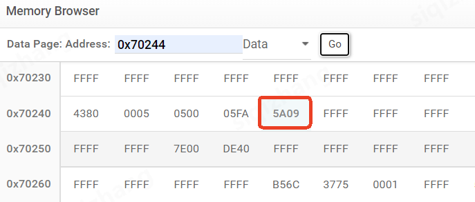
However, when I did an online simulation, before the program ran (Figure 2: Debug view in Code Composer Studio), the GPBPUD register was not all 1s. This caused several IO ports to output a high level. Only when my program initialized the IO pins did the GPBPUD register change to the state where the pull - ups are disabled (values corresponding to pull - up disable).

3. Questions

  • Why is the GPBPUD register not in the expected all - 1s state (pull - ups disabled) before the program initializes the IO? Is there something about the boot process or default register values that I'm missing?
  • How can I ensure that the GPIO pull - up state is as described in the datasheet (disabled) right after reset, without waiting for the program's IO initialization?
Attached are the relevant figures:
  • Figure 1: Datasheet excerpt showing GPIOx pull - up should be disabled at reset.
  • Figure 2: Debug view showing GPBPUD register state before program - level IO initialization.
Thanks for your help!
Best regards,
Elena
  • Hi Elena,

    It’s common for the debugger or the boot ROM to configure some GPIO pins for JTAG or other purposes before your application code runs. This can lead to pull-up registers showing values other than what’s expected from a clean reset. If default reset states are critical, consider using a customized startup (e.g., modify the codestart branch or reset ISR) to configure the pull-ups before any CCS or ROM routines affect them.

    To ensure pull-ups off after reset, the most reliable approach is to explicitly set GPBPUD to the desired value as the very first instruction in your initialization code used by the bootloader or SYSBIOS.

    Best Regards,

    Masoud

  • Hi Masoud,

    Thank you very much for your detailed explanation and suggestions. However, I'm still facing a challenge that I'd like to clarify further.

    The key concern I have is actually about the GPIO state during the programming/flash process itself, not just after reset or during program execution. Currently, when I'm flashing the program to the TMS320F280034 via CCS, several GPIO pins output high levels throughout the programming process, which affects my external circuitry.

    I understand your suggestion about configuring GPBPUD early in the initialization code, but this seems to only take effect after the program starts running. What I need is to prevent these high levels from occurring during the actual flashing procedure when the chip is in programming mode, before any of my application code (including the startup code) executes.

    Could you please provide some guidance on whether there's a way to control the GPIO state during the programming phase? For example:

    • Is there a configuration option in CCS or UniFlash that can set GPIO states before flashing?
    • Are there any hardware-specific registers or boot configuration pins that can influence GPIO behavior during programming?

    Thank you again for your assistance.

    Best regards,
    Elena
  • Hi Elena,

    When you flash from CCS over JTAG, the device is in emulation boot. Before your application ever runs, the Boot ROM and debug connection may touch a few pins. So you can observe levels on some pins even though the datasheet says pull ups are disabled “after reset.”
    CCS can run GEL/init scripts automatically on target connect/reset; those scripts can write the GPIO registers (GPxPUD/GPxDIR/GPxDAT) to a safe state before you load/erase/program. The gel file is used in .ccxml file as:

    Here is the path for .gel file:

    C:\ti\ccs<version>\ccs\ccs_base\emulation\gel

    You can force direction/outputs to safe: set GPxDIR/GPxSET/GPxCLEAR accordingly.
    Overall, while you’re designing, you should review which pins are used by Boot ROM/JTAG and which are boot mode selects; keep critical outputs off those pins if possible.

    Let us know if this resolved the issue.

    Best Regards,

    Masoud

  • Hi Masoud,

    Thank you for your continued support and explanations. I'd like to share some additional details from further checks:

    1. The pin in question is GPIO43, which I've confirmed is a general-purpose IO pin in my design and not related to JTAG or other special functions. This is why the unexpected high level during programming has been particularly confusing.
    2. Regarding the GEL file and package-related configurations you mentioned:
      I'm using the F280034SPN with an LQFP80 package. When reading the TI_OTP_PKG_TYPE address via UniFlash, the data obtained is 0x5A09.I think this is the real reason. In the GEL file, this value corresponds to the "PROBE package" configuration. As a result, in the enable_unbonded_pullups_80_P_pin() function, the GPBPUD register is written as 0x1FFFF27F. — which matches my measured result of 0xDFFFF27F. While there’s a discrepancy in the highest 8 bits, it doesn’t affect since I’m using an 80-pin device.
    3. I attempted to write the GPBPUD register to 0x1FFFFFFF  in the GEL function and found that the issue was resolved — GPIO43 is no longer pulled up during programming.
    However, I still have questions: Based on my understanding, the F280034SPN (LQFP80 package) I'm using should be of the QUAL type, but the value read from the OTP indicates a PROBE type configuration, which is inconsistent with my expectations. Could you explain the differences between these two package types and whether my chip is actually a QUAL type? Will modifying the GEL file to set GPBPUD to 0x1FFFFFFF cause any other unexpected issues or side effects?

    Thank you again for your assistance.

    Best regards,
    Elena
  • Hi Elena,

    The PROBE vs QUAL label in the GEL is not a device life-cycle/quality grade; it’s just how the GEL table encodes a package option so it knows which pins are unbonded. Your F280034SPN (80-pin LQFP) is a production device; the OTP field is only being used by the GEL to decide which pull-ups to touch.

    Is it safe to force GPxPUD = 0x1FFFFFFF in GEL?

    Yes. Writing 1s to GPxPUD disables the internal pull-ups (it does not drive the pins), so forcing all 1s before programming is a safe way to keep your GPIOs from being pulled high by the GEL during flash/program flows. Just make sure any critical outputs are not relying on an internal pull-up during bring-up.

    About GPIO43 specifically, GPIO43 is a normal GPIO on this package (i.e., not a JTAG pin). The reason it went high during programming was the GEL’s unbonded-pullups write, not Boot ROM code.

    Best regards,
    Masoud

  • Hi Masoud,

    Thank you so much for your patience and professional help all along. Your guidance has been a huge relief, as it really solved a big problem for me. I truly appreciate your help—thank you again!

    Best regards,
    Elena
  • Glad to hear the issue has been resolved Thumbsup

    Best Regards,

    Masoud