Other Parts Discussed in Thread: SYSCONFIG, UNIFLASH,
Tool/software:
Hi,
I have an F2800157 Series LaunchPad and I'm confused on how to configure my bootpin/bootmode information in OTP. I know that I will only have to write this once, so I conceive it could be either developing a program or just outputting a HEX file that is loaded once. The HEX file that would just set these values in the OTP would be ideal, as I plan on sending this to my sub to load the part.
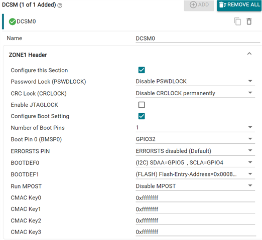
I understand from the 280015x Tech Ref I need to change BOOTDEF0 to 0x07 for I2C mode/FLASH and BMSP0 to GPIO32 - 0x32 (from below).
5.4.3.2 One Boot Mode Select Pin
This use case demonstrates a scenario for an application using one boot mode select pin to select between
booting to Flash or using CAN boot.
- Program the BOOTPIN_CONFIG location in OTP as follows:
- Set BOOTPIN_CONFIG.BMSP0 to a user specified GPIO, such as 0x0 for GPIO0
- Set BOOTPIN_CONFIG.BMSP1 to 0xFF
- Set BOOTPIN_CONFIG.BMSP2 to 0xFF
- Set BOOTPIN_CONFIG.KEY to 0x5A for boot ROM to treat these register bits as valid and use the custom boot table.
- Program the BOOTDEF location options for the device. This essentially sets up a device-specific boot mode table. Refer to Section 5.7.8 for valid BOOTDEF values to set in the table.
- Set BOOTDEF.BOOTDEF0 to 0x02 for CAN 0x07 I2C booting. This sets CAN boot to boot table index 0.
- Set BOOTDEF.BOOTDEF1 to 0x03 for booting to Flash (entry address option 0). This sets Flash boot to boot table index 1.
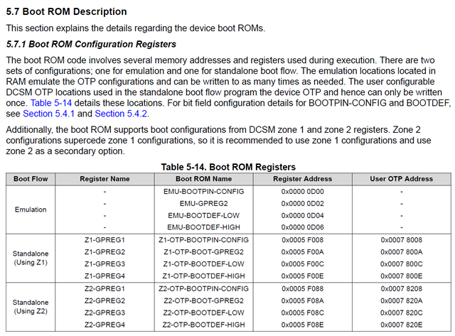
From below (5.8 & 5.7) and above (5.4.3.2) it would appear that I need to write 0xFF32 to address 0x78008 (Z1-GPREG1), 0x5AFF to address 0x78009 (Z1-GPREG1), and 0xFF37 to address 0x7800C (Z1-GPREG3).

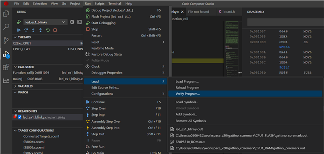
Can you give any hint of how I would accomplish creating the HEX file with CCS 20?
Thanks in advance,
John