Part Number: BOOSTXL-BUCKCONV
Other Parts Discussed in Thread: SFRA, SYSCONFIG
Tool/software:
Hello,
I've been running the labs as per TIDU986a and had a a couple of abnormalities about SFRA:
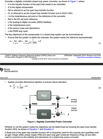
- Plant vs OpenLoop Model:
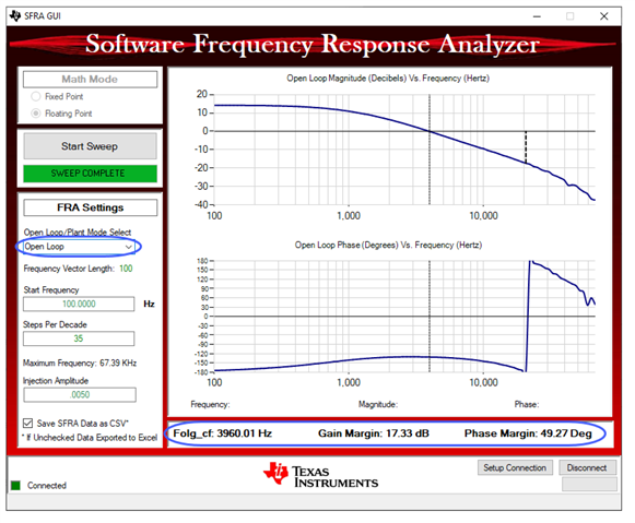
- When I run Lab 1 I expect to get the D to Vo response. The sweeps done by SFRA provide two results: the open-loop transfer function and the plant transfer function. In the context of this test what does open-loop transfer function mean? Because the results from that look very strange if it is the D-to-Vo bode plot of a CCM buck. Here is a screen shot of the SFRA results from the Lab documentation for the open-loop transfer function and the phase starts off at close to -180degrees which is strange.
- When I look at the Plant transfer function this seems more in-line with what I expect the D-to-Vo response to look like from phase perspective. However, the DC gain value seems quite low. The output voltage is about 2.3V and the duty cycle I punched in is 30%. I would expect to see a gain of ~17dB but in the plant bode plot the gain is about 1.7. Would be great if someone could help me understand the results.
- The next thing that I ran into that was a bit strange was when I was looking to see the impact of lower ISR execution rate on my D-to-Vo transfer function. I expect the lower my controller execution frequency the faster my phase roll off would be but I am seeing something quite the opposite. Here is a comparison of the plant bode plots with execution at 200kHz and at 33kHz:
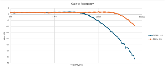
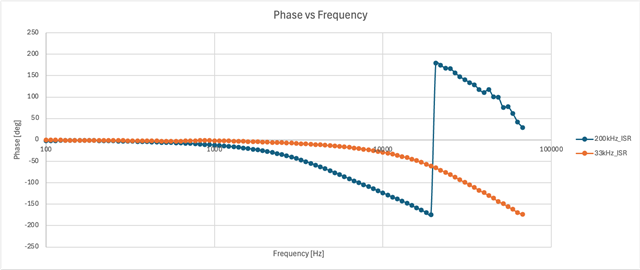
For 33kHz the phase roll off seems to occur at a much higher frequency which is very strange to me. Was wondering if someone could help me understand this result.
NOTE: I modified the project to get the system to run at 33kHz and just to ensure that I did it correctly I put a pin toggle in the ISR and captured it on a scope (the time scale is unchanged and the cursors indicate the ISR frequency with the pin toggle on CH1. CH2 is the output voltage). See below:


Looking forward to some clarification on the SFRA tool!