TMS320F2811: issue programming dsp

Part Number: TMS320F2811

Tool/software:

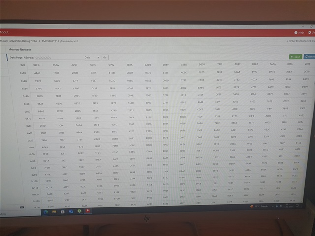
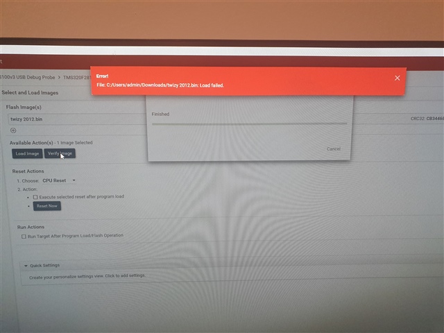
I’m having issues programming the F2811 microcontroller. Something strange is happening: I can read and export the memory from the DSP, but I can’t program it.

I replaced the DSP with a new one, checked all the pins, and confirmed there are no shorts between them. I also verified the JTAG interface connector, and everything looks fine.

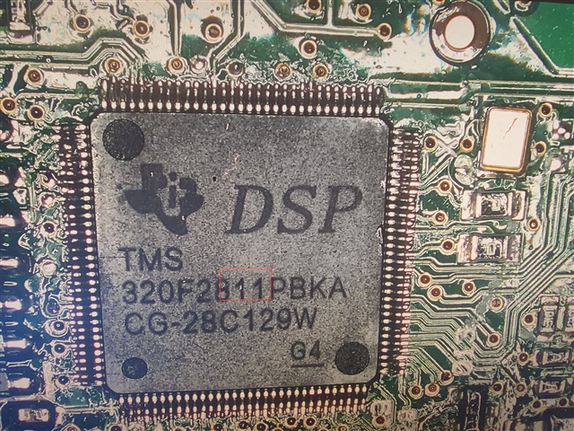
Could anyone help me resolve this problem? I still suspect the microcontroller might be fake or defective. I bought five new F2811 chips from an eBay seller, and my previous ones were ordered from AliExpress.

  • Hello, 

    Can you share an image of the top side of the device(s); I may be able to tell if this are genuine TI devices or not from that marking.

    From an electrical POV, have you verified that VDD3VFL pin is powered to 3.3V(this should be ganged to same net as VDDIO)?  This is the flash power pin, if flash is not programming, but rest of device is working, it may be that this pin is not driven correctly.

    Best,

    Matthew

  • Hi Matthew ,

    Thank you for your reply, i verified the voltage on pin VDD3VFL is fine 3,3v ,i checked also 1,8V .

    Best regards sascha 

  • Sascha,

    Based on what I can see in our history I don't think this is a valid TI device unfortunately.  I can't match up the Lot Code(bottom row) with a known lot code from our records.

    It does look like these are available/in stock on TI.com so you should be able to get some new devices to replace these quickly.

    Best,

    Matthew

  • Thank you very much for your support, Matthew. This may explain the issue I’ve been experiencing.
    Wishing you all the best.

  • Matthew ,

    I have verified that all newly purchased F2811 DSPs are defective — five sourced from an eBay vendor and two from AliExpress. To confirm this, I desoldered a known-good DSP from a donor board and re-soldered it onto my target board. With this replacement device, I was able to successfully program the microcontroller without any issues.

    However, upon power-up, the microcontroller consistently enters bootloader mode (indicated by the LED flashing once long and five times short). This behavior suggests that one or more external components may be faulty, preventing the microcontroller from executing the programmed firmware.

  • I would appreciate any assistance in resolving the issue where the DSP is being forced to start in boot mode

  • Sascha,

    You will need to change the boot mode in order to prevent it from entering bootoader mode; below is from the DS:

    Boot to flash is the one that is most often the default;  if you are having issues connecting a debugger when the device comes up; you may need to activate WIR(Wait in Reset) in the CCS/ccxml tools to prevent the device from executing anything when the debugger is connected.

    Best,

    Matthew

  • Dear Matthew,

    Thank you for your reply. I investigated the issue yesterday and found that the F2811 was configured at boot to send a request to the external EEPROM (25LC640). It appears that some bits or files in the 25LC640 had become corrupted, which caused the DSP to enter bootloader mode when it did not receive a proper response from the EEPROM.

    After reflashing the 25LC640, the problem was resolved.

  • I am facing now with new issue ,the 2811 removedfrom doner board, I was able to erase all sections and then flash new firmware. However, after programming, I noticed that parts of the old application code were still present, which prevented the new firmware from running properly.

    It seems that some memory regions were protected against erasing. Is this due to the Code Security Module (CSM) or OTP areas on the device? If the donor board had set a password, is it impossible to completely erase the chip without knowing it?

    In this situation, is the only reliable option to use a brand-new, blank F2811 device? Or is there any method to fully clear a previously locked device ?

  • Sascha,

    In the regions of old application code, can you view data, or do you see all 0x0000?  If you see all 0x0000, then it is the CSM being activated, if you see actual op codes then the device is unlocked.  I suspect this is unlocked, this device(to my knowledge) doesn't have address bounded CSM, that is all the flash is protected or not, there is no in-between.

    If the previous FW used locations in OTP, then that cannot be undone, regardless of CSM.  Your options are either a new device, or if there is empty space in the OTP, you could re-assign those variables or code regions in your linker file.  The old code will persist, but it will not be used by your updated code. 

    If there is not enough room remaining, then a fresh device is the only choice.

    Best,

    Matthew