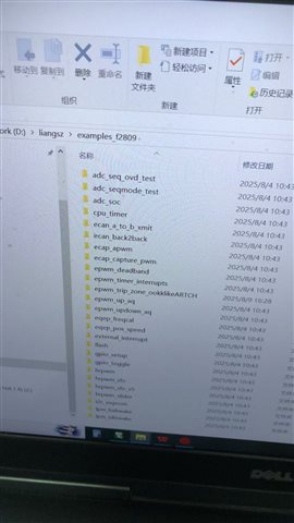
Tool/software:
Especially the third one in the above picture, I don't understand what it means.
The third type seems to also involve PWM. Do you know why ADC and PWM are related and how they are used together?

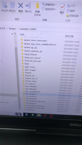
Tool/software:
Especially the third one in the above picture, I don't understand what it means.
The third type seems to also involve PWM. Do you know why ADC and PWM are related and how they are used together?