


Part Number: TMS320F28379D
Other Parts Discussed in Thread: SYSCONFIG
Tool/software:
Hello TMS32 team,
Can my main code and sysconfig be checked to make sure I have the right steps?
As I understand, using the I2C library, I need to use I2C_putData() for x many times, where x is the I2C counter value. Then I issue a START condition, I2C_sendStartCondition().
Now, the part I am confused...do I need to insert a manual STOP command or is that automatically sent? I'm unable to communicate successfully with an NI-8452 device when sending more than 1 byte.
Main c file (see the main while loop for few lines of code):
//#############################################################################
//
// FILE:   spi_ex1_loopback.c
//
// TITLE:  SPI Digital Loopback
// [___ADC__]
//  Master out  |    GPIO63     |  H55 - yellow
//  Master in   |    GPIO64     |  H54 - green
//  CLK         |    GPIO65     |  H47 - red
//  CS          |    GPIO131    |  H58 - orange
//  TMR_SCP_OUT |    GPIO32     |  H2 - scope
//  TIMER_IN    |    GPIO40     |  H50 - from LMK5B
//  START       |    GPIO27     |  H52 - purple
//  RESET       |    GPIO25     |  H51 - blue
//  nDRDY_IN    |    GPIO15     |  H73 - unused
//  [__am64__]
//  Master out  |    GPIO58     |  H15 -
//  Master in   |    GPIO59     |  H14 -
//  CLK         |    GPIO60     |  H7 -
//  CS          |    GPIO61     |  H19 - leave floating
//  Fake CS     |    GPIO125    |  H12 -  Use for 4-byte SPI
//  [__i2c ni__]
//  Master out  |    GPIO104     |  H9 - SCL
//  Master in   |    GPIO105    |  H10 - SDA


//! \addtogroup driver_example_list
//! <h1>SPI Digital Loopback</h1>
//!
//! This program uses the internal loopback test mode of the SPI module. This
//! is a very basic loopback that does not use the FIFOs or interrupts. A
//! stream of data is sent and then compared to the received stream.
//! The pinmux and SPI modules are configure through the sysconfig file.
//!
//! The sent data looks like this: \n
//!  0000 0001 0002 0003 0004 0005 0006 0007 .... FFFE FFFF 0000
//!
//! This pattern is repeated forever.
//!
//! \b External \b Connections \n
//!  - None
//!
//! \b Watch \b Variables \n
//!  - \b sData - Data to send
//!  - \b rData - Received data
//!
//
//#############################################################################
//
// Included Files
//
#include "device.h"
#include "board.h"
#include "ads127l21.h"
#include <stdio.h>
#include <math.h>


__interrupt void nDRDY_IN_GPIO_ISR(void);
__interrupt void timer_IN_GPIO_ISR(void);

const uint8_t g_adcDataSize = 8; //set to powers of 2 for bitshift
uint8_t g_adcDataDiv;
int32_t g_adcDataSum;
int32_t g_adcDataAvg;
int32_t g_adcData[g_adcDataSize];

//
// Main
//
void main(void)
{
    // Initialize device clock and peripherals
    Device_init();
    // Disable pin locks and enable internal pullups.
    Device_initGPIO();
    // Initialize PIE and clear PIE registers. Disables CPU interrupts.
    Interrupt_initModule();
    // Initialize the PIE vector table with pointers to the shell Interrupt
    // Service Routines (ISR).
    Interrupt_initVectorTable();

    // IMPORTANT: Make sure device is powered before setting GPIOs pins to HIGH state.
    // Initialize GPIOs pins used by ADS127L11
    // Initialize SPI peripheral used by ADS127L11
    Board_init();
    ADS127_startUp();
    /* Trigger to start ADC conversion */
    GPIO_setQualificationPeriod(timer_IN_GPIO, 1);


    // Enable Global Interrupt (INTM) and realtime interrupt (DBGM)
    EINT;
    ERTM;


    delay_ms(100);
    uint16_t stat = I2C_getStatus(ni_I2C_BASE);
    while(( stat& I2C_STS_BUS_BUSY) == I2C_STS_BUS_BUSY);
    delay_ms(100);

    while(1)
    {

        I2C_putData(ni_I2C_BASE, 0x4);
        I2C_putData(ni_I2C_BASE, 3);
        I2C_putData(ni_I2C_BASE, 5);
        I2C_sendStartCondition(ni_I2C_BASE);

        delay_ms(1);

    }
}
Sysconfig:
https://e2e.ti.com/cfs-file/__key/communityserver-discussions-components-files/171/spi_5F00_ex1_5F00_loopback.syscfg
Board.c file auto generated from sysconfig:
/*
 * Copyright (c) 2020 Texas Instruments Incorporated - http://www.ti.com
 * All rights reserved.
 *
 * Redistribution and use in source and binary forms, with or without
 * modification, are permitted provided that the following conditions
 * are met:
 *
 * *  Redistributions of source code must retain the above copyright
 *    notice, this list of conditions and the following disclaimer.
 *
 * *  Redistributions in binary form must reproduce the above copyright
 *    notice, this list of conditions and the following disclaimer in the
 *    documentation and/or other materials provided with the distribution.
 *
 * *  Neither the name of Texas Instruments Incorporated nor the names of
 *    its contributors may be used to endorse or promote products derived
 *    from this software without specific prior written permission.
 *
 * THIS SOFTWARE IS PROVIDED BY THE COPYRIGHT HOLDERS AND CONTRIBUTORS "AS IS"
 * AND ANY EXPRESS OR IMPLIED WARRANTIES, INCLUDING, BUT NOT LIMITED TO,
 * THE IMPLIED WARRANTIES OF MERCHANTABILITY AND FITNESS FOR A PARTICULAR
 * PURPOSE ARE DISCLAIMED. IN NO EVENT SHALL THE COPYRIGHT OWNER OR
 * CONTRIBUTORS BE LIABLE FOR ANY DIRECT, INDIRECT, INCIDENTAL, SPECIAL,
 * EXEMPLARY, OR CONSEQUENTIAL DAMAGES (INCLUDING, BUT NOT LIMITED TO,
 * PROCUREMENT OF SUBSTITUTE GOODS OR SERVICES; LOSS OF USE, DATA, OR PROFITS;
 * OR BUSINESS INTERRUPTION) HOWEVER CAUSED AND ON ANY THEORY OF LIABILITY,
 * WHETHER IN CONTRACT, STRICT LIABILITY, OR TORT (INCLUDING NEGLIGENCE OR
 * OTHERWISE) ARISING IN ANY WAY OUT OF THE USE OF THIS SOFTWARE,
 * EVEN IF ADVISED OF THE POSSIBILITY OF SUCH DAMAGE.
 *
 */

#include "board.h"

//*****************************************************************************
//
// Board Configurations
// Initializes the rest of the modules.
// Call this function in your application if you wish to do all module
// initialization.
// If you wish to not use some of the initializations, instead of the
// Board_init use the individual Module_inits
//
//*****************************************************************************
void Board_init()
{
	EALLOW;

	PinMux_init();
	INPUTXBAR_init();
	GPIO_init();
	I2C_init();
	SPI_init();
	XINT_init();
	INTERRUPT_init();

	EDIS;
}

//*****************************************************************************
//
// PINMUX Configurations
//
//*****************************************************************************
void PinMux_init()
{
	//
	// PinMux for modules assigned to CPU1
	//

	// GPIO131 -> nCS_ADC_OUT_GPIO Pinmux
	GPIO_setPinConfig(GPIO_131_GPIO131);
	// GPIO25 -> nRESET_OUT_GPIO Pinmux
	GPIO_setPinConfig(GPIO_25_GPIO25);
	// GPIO27 -> START_OUT_GPIO Pinmux
	GPIO_setPinConfig(GPIO_27_GPIO27);
	// GPIO15 -> nDRDY_IN_GPIO Pinmux
	GPIO_setPinConfig(GPIO_15_GPIO15);
	// GPIO32 -> timer_scp_GPIO Pinmux
	GPIO_setPinConfig(GPIO_32_GPIO32);
	// GPIO40 -> timer_IN_GPIO Pinmux
	GPIO_setPinConfig(GPIO_40_GPIO40);
	// GPIO125 -> nCS_AM64_OUT_GPIO Pinmux
	GPIO_setPinConfig(GPIO_125_GPIO125);
	//
	// I2CA -> ni_I2C Pinmux
	//
	GPIO_setPinConfig(ni_I2C_I2CSDA_PIN_CONFIG);
	GPIO_setPadConfig(ni_I2C_I2CSDA_GPIO, GPIO_PIN_TYPE_STD | GPIO_PIN_TYPE_PULLUP);
	GPIO_setQualificationMode(ni_I2C_I2CSDA_GPIO, GPIO_QUAL_ASYNC);

	GPIO_setPinConfig(ni_I2C_I2CSCL_PIN_CONFIG);
	GPIO_setPadConfig(ni_I2C_I2CSCL_GPIO, GPIO_PIN_TYPE_STD | GPIO_PIN_TYPE_PULLUP);
	GPIO_setQualificationMode(ni_I2C_I2CSCL_GPIO, GPIO_QUAL_ASYNC);

	//
	// SPIB -> adc_SPI Pinmux
	//
	GPIO_setPinConfig(adc_SPI_SPIPICO_PIN_CONFIG);
	GPIO_setPadConfig(adc_SPI_SPIPICO_GPIO, GPIO_PIN_TYPE_STD);
	GPIO_setQualificationMode(adc_SPI_SPIPICO_GPIO, GPIO_QUAL_SYNC);

	GPIO_setPinConfig(adc_SPI_SPIPOCI_PIN_CONFIG);
	GPIO_setPadConfig(adc_SPI_SPIPOCI_GPIO, GPIO_PIN_TYPE_STD);
	GPIO_setQualificationMode(adc_SPI_SPIPOCI_GPIO, GPIO_QUAL_SYNC);

	GPIO_setPinConfig(adc_SPI_SPICLK_PIN_CONFIG);
	GPIO_setPadConfig(adc_SPI_SPICLK_GPIO, GPIO_PIN_TYPE_STD);
	GPIO_setQualificationMode(adc_SPI_SPICLK_GPIO, GPIO_QUAL_SYNC);

	GPIO_setPinConfig(adc_SPI_SPIPTE_PIN_CONFIG);
	GPIO_setPadConfig(adc_SPI_SPIPTE_GPIO, GPIO_PIN_TYPE_STD);
	GPIO_setQualificationMode(adc_SPI_SPIPTE_GPIO, GPIO_QUAL_SYNC);


}

//*****************************************************************************
//
// GPIO Configurations
//
//*****************************************************************************
void GPIO_init(){
	nCS_ADC_OUT_GPIO_init();
	nRESET_OUT_GPIO_init();
	START_OUT_GPIO_init();
	nDRDY_IN_GPIO_init();
	timer_scp_GPIO_init();
	timer_IN_GPIO_init();
	nCS_AM64_OUT_GPIO_init();
}

void nCS_ADC_OUT_GPIO_init(){
	GPIO_writePin(nCS_ADC_OUT_GPIO, 1);
	GPIO_setPadConfig(nCS_ADC_OUT_GPIO, GPIO_PIN_TYPE_STD);
	GPIO_setQualificationMode(nCS_ADC_OUT_GPIO, GPIO_QUAL_SYNC);
	GPIO_setDirectionMode(nCS_ADC_OUT_GPIO, GPIO_DIR_MODE_OUT);
	GPIO_setControllerCore(nCS_ADC_OUT_GPIO, GPIO_CORE_CPU1);
}
void nRESET_OUT_GPIO_init(){
	GPIO_writePin(nRESET_OUT_GPIO, 1);
	GPIO_setPadConfig(nRESET_OUT_GPIO, GPIO_PIN_TYPE_STD);
	GPIO_setQualificationMode(nRESET_OUT_GPIO, GPIO_QUAL_SYNC);
	GPIO_setDirectionMode(nRESET_OUT_GPIO, GPIO_DIR_MODE_OUT);
	GPIO_setControllerCore(nRESET_OUT_GPIO, GPIO_CORE_CPU1);
}
void START_OUT_GPIO_init(){
	GPIO_writePin(START_OUT_GPIO, 1);
	GPIO_setPadConfig(START_OUT_GPIO, GPIO_PIN_TYPE_STD);
	GPIO_setQualificationMode(START_OUT_GPIO, GPIO_QUAL_SYNC);
	GPIO_setDirectionMode(START_OUT_GPIO, GPIO_DIR_MODE_OUT);
	GPIO_setControllerCore(START_OUT_GPIO, GPIO_CORE_CPU1);
}
void nDRDY_IN_GPIO_init(){
	GPIO_setPadConfig(nDRDY_IN_GPIO, GPIO_PIN_TYPE_STD | GPIO_PIN_TYPE_PULLUP);
	GPIO_setQualificationMode(nDRDY_IN_GPIO, GPIO_QUAL_SYNC);
	GPIO_setDirectionMode(nDRDY_IN_GPIO, GPIO_DIR_MODE_IN);
	GPIO_setControllerCore(nDRDY_IN_GPIO, GPIO_CORE_CPU1);
}
void timer_scp_GPIO_init(){
	GPIO_writePin(timer_scp_GPIO, 0);
	GPIO_setPadConfig(timer_scp_GPIO, GPIO_PIN_TYPE_STD);
	GPIO_setQualificationMode(timer_scp_GPIO, GPIO_QUAL_SYNC);
	GPIO_setDirectionMode(timer_scp_GPIO, GPIO_DIR_MODE_OUT);
	GPIO_setControllerCore(timer_scp_GPIO, GPIO_CORE_CPU1);
}
void timer_IN_GPIO_init(){
	GPIO_setPadConfig(timer_IN_GPIO, GPIO_PIN_TYPE_STD | GPIO_PIN_TYPE_PULLUP);
	GPIO_setQualificationMode(timer_IN_GPIO, GPIO_QUAL_SYNC);
	GPIO_setDirectionMode(timer_IN_GPIO, GPIO_DIR_MODE_IN);
	GPIO_setControllerCore(timer_IN_GPIO, GPIO_CORE_CPU1);
}
void nCS_AM64_OUT_GPIO_init(){
	GPIO_writePin(nCS_AM64_OUT_GPIO, 1);
	GPIO_setPadConfig(nCS_AM64_OUT_GPIO, GPIO_PIN_TYPE_STD);
	GPIO_setQualificationMode(nCS_AM64_OUT_GPIO, GPIO_QUAL_SYNC);
	GPIO_setDirectionMode(nCS_AM64_OUT_GPIO, GPIO_DIR_MODE_OUT);
	GPIO_setControllerCore(nCS_AM64_OUT_GPIO, GPIO_CORE_CPU1);
}

//*****************************************************************************
//
// I2C Configurations
//
//*****************************************************************************
void I2C_init(){
	ni_I2C_init();
}

void ni_I2C_init(){
	I2C_disableModule(ni_I2C_BASE);
	I2C_initController(ni_I2C_BASE, DEVICE_SYSCLK_FREQ, ni_I2C_BITRATE, I2C_DUTYCYCLE_50);
	I2C_setConfig(ni_I2C_BASE, I2C_CONTROLLER_SEND_MODE);
	I2C_disableLoopback(ni_I2C_BASE);
	I2C_setOwnAddress(ni_I2C_BASE, ni_I2C_OWN_ADDRESS);
	I2C_setTargetAddress(ni_I2C_BASE, ni_I2C_TARGET_ADDRESS);
	I2C_setBitCount(ni_I2C_BASE, I2C_BITCOUNT_8);
	I2C_setDataCount(ni_I2C_BASE, 3);
	I2C_setAddressMode(ni_I2C_BASE, I2C_ADDR_MODE_7BITS);
	I2C_disableFIFO(ni_I2C_BASE);
	I2C_setEmulationMode(ni_I2C_BASE, I2C_EMULATION_FREE_RUN);
	I2C_enableModule(ni_I2C_BASE);
}

//*****************************************************************************
//
// INPUTXBAR Configurations
//
//*****************************************************************************
void INPUTXBAR_init(){
	myINPUTXBARINPUT0_init();
	myINPUTXBARINPUT1_init();
}

void myINPUTXBARINPUT0_init(){
	XBAR_setInputPin(myINPUTXBARINPUT0_INPUT, myINPUTXBARINPUT0_SOURCE);
}
void myINPUTXBARINPUT1_init(){
	XBAR_setInputPin(myINPUTXBARINPUT1_INPUT, myINPUTXBARINPUT1_SOURCE);
}

//*****************************************************************************
//
// INTERRUPT Configurations
//
//*****************************************************************************
void INTERRUPT_init(){

	// Interrupt Settings for INT_nDRDY_IN_GPIO_XINT
	// ISR need to be defined for the registered interrupts
	Interrupt_register(INT_nDRDY_IN_GPIO_XINT, &nDRDY_IN_GPIO_ISR);
	Interrupt_disable(INT_nDRDY_IN_GPIO_XINT);

	// Interrupt Settings for INT_timer_IN_GPIO_XINT
	// ISR need to be defined for the registered interrupts
	Interrupt_register(INT_timer_IN_GPIO_XINT, &timer_IN_GPIO_ISR);
	Interrupt_disable(INT_timer_IN_GPIO_XINT);
}
//*****************************************************************************
//
// SPI Configurations
//
//*****************************************************************************
void SPI_init(){
	adc_SPI_init();
}

void adc_SPI_init(){
	SPI_disableModule(adc_SPI_BASE);
	SPI_setConfig(adc_SPI_BASE, DEVICE_LSPCLK_FREQ, SPI_PROT_POL0PHA0,
				  SPI_MODE_CONTROLLER, adc_SPI_BITRATE, adc_SPI_DATAWIDTH);
	SPI_setPTESignalPolarity(adc_SPI_BASE, SPI_PTE_ACTIVE_LOW);
	SPI_enableHighSpeedMode(adc_SPI_BASE);
	SPI_disableFIFO(adc_SPI_BASE);
	SPI_disableLoopback(adc_SPI_BASE);
	SPI_setEmulationMode(adc_SPI_BASE, SPI_EMULATION_STOP_AFTER_TRANSMIT);
	SPI_enableModule(adc_SPI_BASE);
}

//*****************************************************************************
//
// XINT Configurations
//
//*****************************************************************************
void XINT_init(){
	nDRDY_IN_GPIO_XINT_init();
	timer_IN_GPIO_XINT_init();
}

void nDRDY_IN_GPIO_XINT_init(){
	GPIO_setInterruptType(nDRDY_IN_GPIO_XINT, GPIO_INT_TYPE_FALLING_EDGE);
	GPIO_setInterruptPin(nDRDY_IN_GPIO, nDRDY_IN_GPIO_XINT);
	GPIO_enableInterrupt(nDRDY_IN_GPIO_XINT);
}
void timer_IN_GPIO_XINT_init(){
	GPIO_setInterruptType(timer_IN_GPIO_XINT, GPIO_INT_TYPE_RISING_EDGE);
	GPIO_setInterruptPin(timer_IN_GPIO, timer_IN_GPIO_XINT);
	GPIO_enableInterrupt(timer_IN_GPIO_XINT);
}
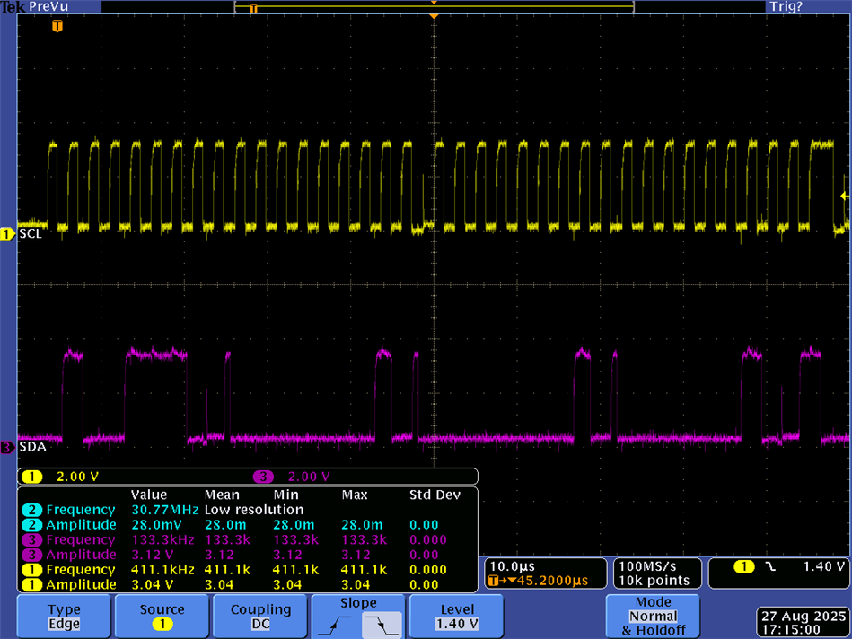
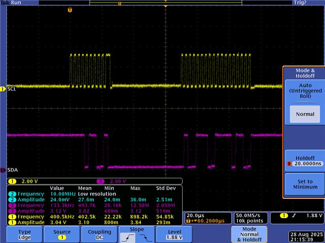
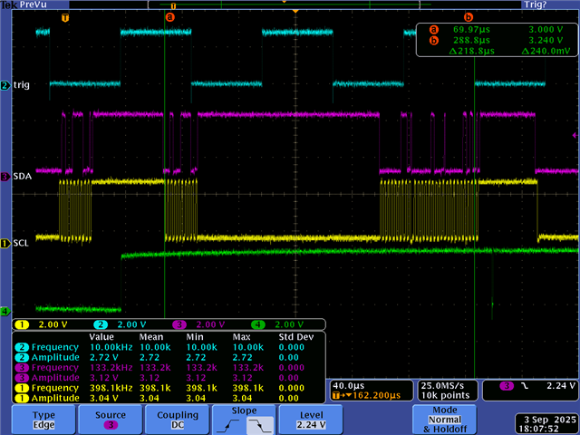
Edit [8/27]: I wanted to add that I can receive data but the bytes received are not correct. For example, if I set the counter to 3 and send 3 bytes [0x1, 0x2, 0x3] then I receive them out of order. This is what I read from the NI I2C slave/peripheral device after 10 sets of 3-byte data are sent. I tried sending a stop command right after sending the start command. Still have same issue.
['0x1', '0x3', '0x3']
['0x0', '0x0', '0x0']
['0x3', '0x3', '0x3']
['0x0', '0x0', '0x0']
['0x3', '0x2', '0x1']
['0x0', '0x0', '0x0']
['0x3', '0x3', '0x3']
['0x0', '0x0', '0x0']
['0x1', '0x1', '0x3']
['0x0', '0x0', '0x0']
Example scope shot:



 . From a C2000 perspective, you can try removing any delays if you have any.