TMS320F28388D: XF28388DZWTS - Programming the device using third party programmer

Part Number: TMS320F28388D
Other Parts Discussed in Thread: C2000WARE

Tool/software:

Hi, 

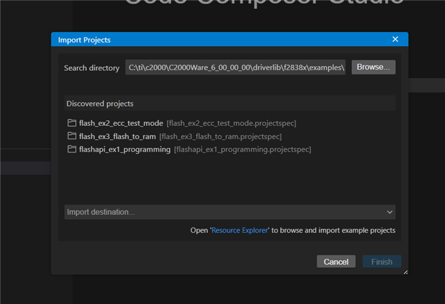
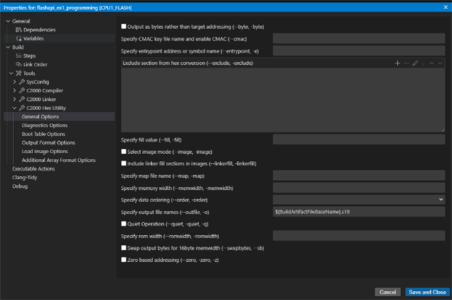
Can you share guidelines on how to program the flash and OTP of the device.

I did look into the CCS example files. I see it is for 176 QFP package. Is there a seperate one for the 337 BGA pacakge,

This device is new to me. So can you please explain the steps on programming the flash and OTP of the device using a third party programmer. Thanks!

  • Hi Vigita,

    The steps to programming the flash and OTP for a device using a third party programmer will vary based on the third party programmer used. Which 3P programmer do you wish to proceed with? 

    Thanks and regards,

    Charles

  • Programmer from BPM Microsystem

  • Hi Vigita,

    I've looked at the BPM Microsystem device search and it says that TMS320F28386DPTPQ device is supported. If you are using the F28388D device variant, it should be similarly programmable. The Programmer Quick Start Guide details how to use the programmer for the 2900, 2900L and 19000 devices.

    Thanks and regards,

    Charles

  • Yes, we are aware that the 176QFP device is supported, but the BGA module design is a bit different compared to QFP design and the QFP is old support, and we are not able to find notes on how that device was supported. Kindly assist us.

  • Hi Vigita,

    Can check with my team on this.

    Thanks and regards,

    Charles

  • Hi Vigita,

    Can you explain a bit more on what the difference is between the QFP and BGA design for your programming usage? They should both have the same die being used. Also, what specific BPM Microsystems programmer are you trying to use?

    Thanks and regards,

    Charles

  • We need to support on 8th and 9th gen.

    I see that the QFP package that we already supported is using parallel Boot IO and using the first 8 GPIO pins for communications.

    Since we have already supported the QFP package, the plan was to use the bootcode written for that device, by using the equivalent pins for BGA device.

    Now the BGA module design that is done is a bit different. In the current BGA module design, I do not see access to the all the first 8 GPIO pins.

    So now, I cannot use the already existing bootcode.

    I was able to find the flashapi_ex1_programming folder for the QFP package that was supported. I have attached it here. 

    Now when I try to build this folder if in CCS to see if the .s19 output is same as used in the algorithm, I see that the build is failing.

    I am kind of stuck in this step and need guidance from you. Kindly assist us and explain us if we are missing any steps. Thanks!

    flashapi_ex1_programming-20250915T071135Z-1-001.zip

  • Hi Vigita,

    I believe that the build structure of the given flash API example has changed. Can you download the latest version of C2000Ware and try generating the project for this device?

    Thanks and regards,
    Charles

  • I have CCS 20.2.0. I created my folder on local. Added that to the workspace.

    Then I went to file-> Import Project. Browse

    Is this the correct path 'C:\ti\c2000\C2000Ware_6_00_00_00\driverlib\f2838x\examples\c28x\flash\CCS'?

    When I select this path, I see three projects loaded. Do I need to choose only flashapi_ex1_programming?

  • Hi Vigita,

    Yes, you can just select the flashapi_ex1_programming example and import that project into the workspace.

    Thanks and regards,

    Charles

  • okay. Done. What will be the next step?

  • Next step would be to configure the generated output for this project. This can be done by going to:

    1. Right-click the project in CCS and go to the Properties tab.

    2. Enable the C2000 Hex Utility.

    3. Go to the C2000 Hex Utility Output Format Options and select the Motorola S hex option to generate the .s19 record output file.

    The algorithm that requires this .s19 format is within the BPM Programmer software?

    Thanks,

    Charles

  • OKay. So here is what I did.

    I imported the flashapi_ex1_programming

    I selected the motorola m3 format

    I did not change anything in the files

    Then I did a build.

    I didnt see any .s19 generated.

    Then I updated the ‘specify output file name’

    I did a build again. I see a .s19 file in device folder

    This is what I understand now.

    I set the gpio72 and gpio84 to low..parallel boot mode

    Then using gpio 89 90 58 59 60 61 62 88, I send the bootcode to the device. I will be using gpio 91 and 92 as communication signals between my programmer and the device.

    Please let me know if my understanding is correct. Thanks!

    What will be the next step after that.

    How do I make this code to erase or program, or read my flash? What commands should I send, and which pins should I use to send and receive to and from flash?

  • Hi Vigita,

    Glad you were able to generate the .s19 record format. This flash API example goes through the possible operations that the Flash API uses for erase and program.

    >I set the gpio72 and gpio84 to low..parallel boot mode. Then using gpio 89 90 58 59 60 61 62 88, I send the bootcode to the device. I will be using gpio 91 and 92 as communication signals between my programmer and the device.

    So you are sending the Flash API example to the device using parallel boot mode with the BPM Programmer? The 9th gen BPM programmer guide does not explicitly state the required device bootmode.  I haven't used this programmer before, but can look into it with more detail. If you are able to see and confirm the code as sent, then this may be the correct way. 

    >How do I make this code to erase or program, or read my flash? What commands should I send, and which pins should I use to send and receive to and from flash?

    You can consult with the Flash API guide for F28388D devices to learn more about the commands for flash programming.

    You also have stated that you wish to use pins to send and receive data to and from flash. Do you intend this to be used as a flash kernel over Parallel Boot communication? If yes, then would the data need to be sent over the same Parallel Boot GPIOs used? And if so, would this kernel communicate with the BPM software programmer? Some clarity here is needed.

    Thanks and regards,

    Charles

  • Let me explain what I see on the algo that is used for the QFP package that we already supported. 

    There is this .s19 file which is converted to array(I assume this is the bootcode).

    Using our programmer, I see that we do the following from programmer side, 

    1.  gpio72 gpio84 are set low

    2. gpio91 floated. gpio92 is high.

    3. For every word:

    3.1. For the LSB byte we check if gpio91 is low from device. If low, we send the byte via gpio 89 90 58 59 60 61 62 88 pins and set gpio92 low. Then we check if gpio91 is high, and if high, we set gpio92 high. 

    3.2. For the MSB byte we check if gpio91 is low. If low, we send the byte via gpio 89 90 58 59 60 61 62 88 pins and set gpio92 low. Then we check if gpio91 is high, and if high, we set gpio92 high. 

    4. Step 3 is repeated until the whole bootcode array is sent to the device.

    Up until this, I understand it should be correct, because I see this in the reference manual.

    I dont understand what is happening after this in the algo that is already writen for the QFP device.

    For example let me explain what I see in the Read operation:

    1. After bootcode is sent, GPIO72 and GPIO66 are set high. A short delay is given.

    2. GPIO66 is set low. GPIO69 is checked if it is low. When low, data is read from GPIO0-GPIO7 pins. Then GPIO66 is set high again. GPIO69 is checked if it is high. The expected data read back from GPIO0-GPIO7 is 0x00

    3. Step 2 is repeated again, now the expected data read back is 0xFF

    4. Step 2 is repeated again, now the expected data read back is 0x55.

    I assume these are something written in the .c in CCS by the previous engineer who worked on this. I would like to know how I ca do this, or does the example code in CCS already has something that I can use without writing complicated code. Or if I give my requiremenets, (for example. if I send data 0x16 to the device, I want the flash to be erased) to you, can you write me the necessary code that I can use.

    If possible, can you arrange a google meeting. This device is very new to me. Thanks!

    I assu

  • Hi,

    I'll be able to see more to this inquiry by tomorrow's time. I do think a meeting should be arranged for this, likely some time next week. Have accepted your friend request. Thanks for your patience on this issue.

    Regards,

    Charles

  • Hi Charles.

    Let me know if we can meet tomorrow or Wednesday (Oct 7th or Oct 8th 2025). I am in IST time zone. Thanks!

  • Hi Vigita,

    Upon further analysis, it seems that this project requires internal knowledge of BPM Microsystems programmer, therefore cannot proceed with a meeting.

    If it is felt this requires more input on the TI side, feel free to create another thread.

    Thanks and regards,

    Charles

  • Hi Charles,

    Can you kindly explain why internal knowledge of BPM Microsystems programmer is needed to assits us?

  • Hi Vigita, it appears your questions are more to do with porting the BPM implementation of your predecessor than specific questions about our device, SW, or tools.  We are not in a position to directly contribute to the implementation or development of your application.  If you have specific questions about our device, SW, or tools then we can answer those.  I'm sorry we are unable to do more here but our expertise is with the TI products and cannot go deep into the BPM application.

    Best regards,

    Joe