LAUNCHXL-F28379D: Consultation on ADC Sampling Error

Part Number: LAUNCHXL-F28379D

Tool/software:

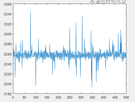
I need to perform fault diagnosis on the motor now and require a highly accurate current value. The zero position voltage measured by the current sensor is very stable, but after entering the ADC module of the f28379d, the measured current error is very large. The measured current has an error of about ±1A, that is, there is an error of 30/4096 during ADC sampling, which cannot meet the requirements of my fault diagnosis. May I ask if this is a problem with the chip or the development board?

  • Wu,

    If I use the MAX errors for gain/offset/INL from the DS I would expect a ~7LSB error natively(pessimistically), so the 30LSB you are seeing is too high to be just from the ADC.

    Here are a few things to try:

    1. Debug Tips: I would suggest making a small program to only sample the ADC, and intentionally over sample the signal of interest.  Maybe capture 100 samples in a row.  Look at the data in Excel and note the code spread.  For this converter, for an ideal DC input, you want to see something like 4 or 5 codes max of distribution to know that the signal is being captured correctly.  If you see a bigger code spread, it means there is noise coupling; either though improper drive strength/cap charge time(see #2/#3 below), or just noise in general on the signal(see #4 below).  For this case, perhaps pick a known DC input, a AA battery is good for this, as it is 1.5V DC source, with no external noise sources.  Once you get this to sample good, change over to your current sensor, and see if things are still OK, or if there is mis-match.
    2. Increase the ACQPS; this is the sample/hold time to charge the ADC internal sampling capacitor.  If there is some impedance mis-match on the signal fed into the ADC it will result in the cap not accurately capturing the voltage on the pin.  Try to increase this value(maybe by an order of 10) to see if you get better error on your voltage conversion
    3. Use the same trigger to initiate a multiple conversions on the same channel, for experimentation purposes try all 16 SOCs from same trigger.  If you see the ADC result the same for all the samples, then the ACQPS is probably OK.  If you see the ADC result trending, then converging it means the ACQPS is too small.  By sampling back to back we are more accurately charging the S/H converter, vs giving it a chance to discharge between samples.
    4. Oversample, in the case of noise we can oversample and average out the noise.  This will decrease your effective sample rate, but if there is spurious noise on the signal it can help dampen it.
    5. Filtering, if you think this is related to noise from the current sensor(vs the DC source); then you can place some type of filter inline to help get rid of the noise as well
    6. System noise: If you see the small ADC testcase looking good, but then in your system the error goes back up; then there may be noise coupling from the system.  Look out for things like the ADC sample placed close to FETs switching in time, you can try to change when the ADC samples to see if it helps.  Since this is a LP, you may try a different ADC channel to see if some proximity to a GPIO that you are using is causing the noise.
    7. Offset correction; there should be a function in driverLIB/C2000 Ware to self correct the offset of the ADC.  The MAX for this error is only 4LSBs, but it can't hurt to see if this helps.

    Best,

    Matthew


  • Hello, I tried it as per your suggestion. I tested it with the ADC tutorial of TI. The specific tutorial link is here. dev.ti.com/.../c2000_lab_adc.html
    The test results are the same as before. There is still a significant fluctuation.The specific effect is as shown in Figure 1.
    In addition, I conducted a test using a No. 7 dry battery, and the outcome was the same. The digital signal values obtained still fluctuated.
    Also, regarding the ACQPS you mentioned, is it the Sample Window [SYSCLK counts] in syscfg, as shown in Figure 2? I changed it from 20 to 200, but there was no change.
    All the tests I mentioned above were carried out on the f28379D development board, without any additional complex hardware environment. Moreover, I have four f28379D development boards at hand and tried them all, but the results were not good. Could you please help me analyze this again? Is it a problem with the development board itself?Thank you for the response.

  • Can you try 2 things:

    1)With the code as-is from lab, increase the ADC clock divider from 4 to 8 and see if there is any improvement

    2)Remove the LED toggle from this code and see if there is any improvement.

    Also, could  you probe the output of the amplifiers, that supply VREFHI to the device, and let me know what voltage you read?

    Best,

    Matthew