TMS320F280039:F280039

Part Number: TMS320F280039

Tool/software:

Hi:

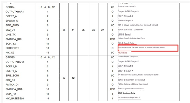
There is a phenomenon here where the chip cannot boot when GPIO25 is powered on in pull-down state, but it can boot when in pull-up state. Is this related to GPIO24?  The above picture indicates:Error state output. This signal requires an external pull-down resistor.Please ask the expert to help answer this, thank you!

  • Hello Tony,

    The default boot-mode pins are GPIO24 and GPIO32 (not GPIO25) right after reset. If both = 1, the device boots to Flash. Any other combination selects other modes (CAN/SCI/Wait), which can look like “no boot.” Please make sure your board straps put GPIO24=1 and GPIO32=1 at power-up/reset.

    GPIO25 is not a boot-select pin. If pulling it down prevents boot, it usually means the pull-down network or connected circuitry is loading or coupling into the boot pins (GPIO24/32) or holding some other critical signal (e.g., reset/NMI domain) in the wrong state during the sampling window. Measure the actual logic levels of GPIO24 and GPIO32 at the moment XRSn releases; one of them is likely being dragged low.

    About the ERRORSTS signal (the device “error status” output), it is an output that can be routed to a set of specific GPIOs. It’s not intended to be driven by external logic. If it is implemented as an open-drain/active-low style output on your design, it typically uses a pull-up so the device can pull it low to signal an error. Double-check the exact pin mapping and biasing for your device/board; do not strap that net with a strong pull-down that could fight the output driver or back-power pins at reset.

    Best Regards,

    Masoud