This thread has been locked.

If you have a related question, please click the "Ask a related question" button in the top right corner. The newly created question will be automatically linked to this question.

TMS320F280037C: CLB documentation

Part Number: TMS320F280037C
Other Parts Discussed in Thread: SYSCONFIG, C2000WARE

Tool/software:

The CLB_HLC_EVEMT_SEL register, as shown in Figure 32-47 in SPRIW9C, directs you to the Static Switch Block Output Mux Table for field definitions.  I can't find a table with that name. Does anyone know where it is?

I'm having trouble getting a filtered GPIO input into the HLC.  I am using the steps outlined at the end of section 9.1 of SPRACL3 to configure the input signal path and using syscfg to set the HLC event inputs to Boundary input 0,1, and 2. 

GPIO_setAnalogMode(252U, GPIO_ANALOG_DISABLED);
    GPIO_setPinConfig(GPIO_252_GPIO252);
    GPIO_setMasterCore(252U, GPIO_CORE_CPU1);
    GPIO_setDirectionMode(252U, GPIO_DIR_MODE_IN);
    GPIO_setPadConfig(252U, GPIO_PIN_TYPE_STD);
    GPIO_setQualificationMode(252U, GPIO_QUAL_ASYNC);
    //CLB
    XBAR_setInputPin(INPUTXBAR_BASE,XBAR_INPUT1, 252U); //use xbar input to route to CLB
    // Configure CLB-XBAR AUXSIG0 as INPUT1
    XBAR_setCLBMuxConfig(XBAR_AUXSIG0, XBAR_CLB_MUX01_INPUTXBAR1);
    XBAR_enableCLBMux(XBAR_AUXSIG0, XBAR_MUX01);
    CLB_configLocalInputMux(CLB1_BASE, CLB_IN0, CLB_LOCAL_IN_MUX_GLOBAL_IN);
    CLB_configGlobalInputMux(CLB1_BASE, CLB_IN0, CLB_GLOBAL_IN_MUX_CLB_AUXSIG0);
    CLB_configGPInputMux(CLB1_BASE, CLB_IN0, CLB_GP_IN_MUX_EXTERNAL);

Syscfg defines TILE0_HLC_EVENT_SEL = 0x6b38.  That sets event 0 to 24 which doesn't make much sense based on any table I can find.

Thanks

  • It appears the correct table is table 32.5 labeled 'Output Table' in section 32.4.1 titled 'Static Switch Block'.

    Fig 32.6 labeled 'Input Table', lists the inputs to each submodule but does not show the HLC submodule. 

    Fig 32.10 'CLB Tile Submodules' in section 32.4 contains a block labeled 'Reconfigurable Switch Block' but not a 'Static Switch Block'.  The text in section 32.4 refers to a 'Static Switch Block' that 'provides dynamic connectivity between all of the blocks' but does not mention the 'Reconfigurable Switch Block' in figure 32.10.  

    I'm assuming for now that 'Reconfigurable Switch Block' is the same as 'Static Switch Block', has a 32 bit wide output bus that is not reconfigurable.  Input selection to each block is provided by a mux at the input of the block, and each input has its own mux.  The HLC has access to the same signals as the other submodules listed in table 32.6 and they connect to the Event 1-4.

  • Another related question.

    Fig 32-10 shows an unlabeled bidirectional bus between the HLC and CLB Tile Submodules. 

    In fig 32-19 in section 32.4.7 'High Level Controller (HLC)' the input bus to the HLC is labeled 'Event bus containing outputs of all the other Cell sub-blocks and external inputs'. 

    Is the bus in fig 32-19 the same as the switch block output in figure 32-10?

  • FWIW all I want to do is take 3 GPIO inputs, filter to output a pulse on all transitions (high to low or low to high), route to the HLC, and trigger an interrupt on each transition. It seems like it should be fairly simple, but I'm not getting any interrupts.  I'm assuming the inputs are not routed correctly, but it could be something else.  

    Thanks

  • I believe the Static Switch Block Output Mux Table is referring to the "CLB Output Signal Multiplexer Table" in the Technical Reference Manual for F28003x, apologies for the confusion.

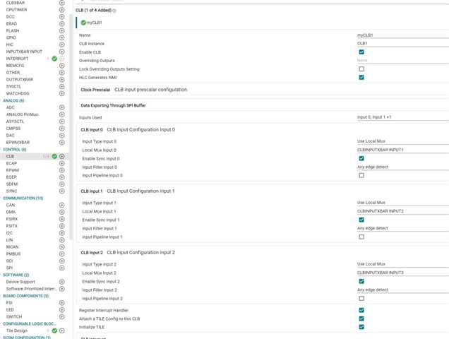
    Could you show the SysConfig GUI options you selected to generate this code?

    Thank you,

    Luke

  • Give me a minute to put everything back in sysconfig.  I removed all input routing from sysconfig and attempted to use clb_ex11_interrupt_tag and its documentation as a template.  

    I should have mentioned that I'm referencing SPRUIW9C – OCTOBER 2021 – REVISED MARCH 2024 technical reference manual. 

    Thanks

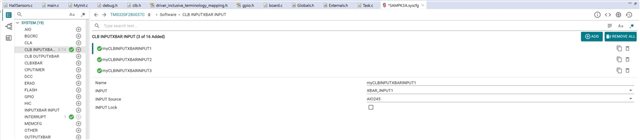
  • CLBInputXBar

    CLBInputs

    CLBInterrupt

    CLB HLC

    input pins are setup in code

    GPIO_setPinConfig(GPIO_252_GPIO252);
    GPIO_setAnalogMode(252U, GPIO_ANALOG_DISABLED);
    GPIO_setDirectionMode(252U, GPIO_DIR_MODE_IN);
    GPIO_setPadConfig(252U, GPIO_PIN_TYPE_STD);
    GPIO_setControllerCore(252U, GPIO_CORE_CPU1);
    GPIO_setQualificationMode(252U, GPIO_QUAL_SYNC); //was async

    Thanks

  • Can you make sure the "Initialize TILE" option is selected in the CLB GUI and add AIOs on the left panel for each AIO you want to use(this appears to be missing from your configuration)? Also double check that a signal is going to the correct AIOs that you have selected.

  • Initialize Tile is selected, and I have confirmed it is called in Board_Init().  I stepped through it in the debugger this morning.  The pin configuration is in code.  I added the code for AIO252 pin configuration after the screenshots of sysconfig.   

    Here is the code setting up the AIOs

    void VavleMotorHallsInit(void)
    {
        // ECAP1 = Valve Motor Hall A   || Pin 32 || AIO252 || XBar Input 4 ||
        GPIO_setPinConfig(GPIO_252_GPIO252);
        GPIO_setAnalogMode(252U, GPIO_ANALOG_DISABLED);
        GPIO_setDirectionMode(252U, GPIO_DIR_MODE_IN);
        GPIO_setPadConfig(252U, GPIO_PIN_TYPE_STD);
        GPIO_setControllerCore(252U, GPIO_CORE_CPU1);
        GPIO_setQualificationMode(252U, GPIO_QUAL_SYNC); //was async
    //    //CLB
    //    XBAR_setInputPin(INPUTXBAR_BASE,XBAR_INPUT1, 252U); //use xbar input to route to CLB
    //    // Configure CLB-XBAR AUXSIG0 as INPUT1
    //    XBAR_setCLBMuxConfig(XBAR_AUXSIG0, XBAR_CLB_MUX01_INPUTXBAR1);
    //    XBAR_enableCLBMux(XBAR_AUXSIG0, XBAR_MUX01);
    //    CLB_configLocalInputMux(CLB1_BASE, CLB_IN0, CLB_LOCAL_IN_MUX_GLOBAL_IN);
    //    CLB_configGlobalInputMux(CLB1_BASE, CLB_IN0, CLB_GLOBAL_IN_MUX_CLB_AUXSIG0);
    //    CLB_configGPInputMux(CLB1_BASE, CLB_IN0, CLB_GP_IN_MUX_EXTERNAL);
    
    
        // ECAP2 = Valve Motor Hall B   || Pin 31 || AIO245 || XBar Input 5 ||
        GPIO_setAnalogMode(245U, GPIO_ANALOG_DISABLED);
        GPIO_setPinConfig(GPIO_245_GPIO245);
        GPIO_setControllerCore(245U, GPIO_CORE_CPU1);
        GPIO_setDirectionMode(245U, GPIO_DIR_MODE_IN);
        GPIO_setPadConfig(245U, GPIO_PIN_TYPE_STD);
        GPIO_setQualificationMode(245U, GPIO_QUAL_ASYNC);
    //    //CLB
    //    XBAR_setInputPin(INPUTXBAR_BASE,XBAR_INPUT2, 245U); //use xbar input to route to CLB
    //    // Configure CLB-XBAR AUXSIG0 as INPUT1
    //    XBAR_setCLBMuxConfig(XBAR_AUXSIG1, XBAR_CLB_MUX01_INPUTXBAR1);
    //    XBAR_enableCLBMux(XBAR_AUXSIG1, XBAR_MUX02);
    //    CLB_configLocalInputMux(CLB1_BASE, CLB_IN1, CLB_LOCAL_IN_MUX_GLOBAL_IN);
    //    CLB_configGlobalInputMux(CLB1_BASE, CLB_IN1, CLB_GLOBAL_IN_MUX_CLB_AUXSIG1);
    //    CLB_configGPInputMux(CLB1_BASE, CLB_IN1, CLB_GP_IN_MUX_EXTERNAL);
    
    
        //ECAP3 = Valve Motor Hall C   || Pin 30 || AIO251 || XBar Input 6 ||
        GPIO_setAnalogMode(251U, GPIO_ANALOG_DISABLED);
        GPIO_setPinConfig(GPIO_251_GPIO251);
        GPIO_setControllerCore(251U, GPIO_CORE_CPU1);
        GPIO_setDirectionMode(251U, GPIO_DIR_MODE_IN);
        GPIO_setPadConfig(251U, GPIO_PIN_TYPE_STD);
        GPIO_setQualificationMode(251U, GPIO_QUAL_ASYNC);
    //    //CLB
    //    XBAR_setInputPin(INPUTXBAR_BASE,XBAR_INPUT3, 251U); //use xbar input to route to CLB
    //    // Configure CLB-XBAR AUXSIG2 as INPUT3
    //    XBAR_setCLBMuxConfig(XBAR_AUXSIG2, XBAR_CLB_MUX01_INPUTXBAR1);
    //    XBAR_enableCLBMux(XBAR_AUXSIG2, XBAR_MUX03);
    //    CLB_configLocalInputMux(CLB1_BASE, CLB_IN2, CLB_LOCAL_IN_MUX_GLOBAL_IN);
    //    CLB_configGlobalInputMux(CLB1_BASE, CLB_IN2, CLB_GLOBAL_IN_MUX_CLB_AUXSIG2);
    //    CLB_configGPInputMux(CLB1_BASE, CLB_IN2, CLB_GP_IN_MUX_EXTERNAL);
    
        //myCLB1_init();
        //initTILE0(CLB1_BASE);
        //Interrupt_register(INT_CLB1, &clb1ISR);
        Board_init();
    }

    Here is the code from Sysconfig\board.c

    void Board_init()
    {
    	EALLOW;
    
    	PinMux_init();
    	CLB_init();
    	CLB_INPUTXBAR_init();
    	INTERRUPT_init();
    
    	EDIS;
    }
    
    //*****************************************************************************
    //
    // PINMUX Configurations
    //
    //*****************************************************************************
    void PinMux_init()
    {
    	//
    	// PinMux for modules assigned to CPU1
    	//
    	
    
    }
    
    //*****************************************************************************
    //
    // CLB Configurations
    //
    //*****************************************************************************
    void CLB_init(){
    	myCLB1_init();
    }
    
    void myCLB1_init(){
    	CLB_enableNMI(myCLB1_BASE);
    	CLB_setOutputMask(myCLB1_BASE,
    				(0UL << 0UL), true);
    	CLB_enableOutputMaskUpdates(myCLB1_BASE);
    	//
    	// myCLB1 SPI Buffer Configuration
    	//
    	CLB_disableSPIBufferAccess(myCLB1_BASE);
    	CLB_configSPIBufferLoadSignal(myCLB1_BASE, 0);
    	CLB_configSPIBufferShift(myCLB1_BASE, 0);
    	//
    	// myCLB1 CLB_IN0 initialization
    	//
    	// The following functions configure the CLB input mux and whether the inputs
    	// have synchronization or pipeline enabled; check the device manual for more
    	// information on when a signal needs to be synchronized or go through a
    	// pipeline filter
    	//
    	CLB_configLocalInputMux(myCLB1_BASE, CLB_IN0, CLB_LOCAL_IN_MUX_INPUT1);
    	CLB_configGlobalInputMux(myCLB1_BASE, CLB_IN0, CLB_GLOBAL_IN_MUX_EPWM1A);
    	CLB_configGPInputMux(myCLB1_BASE, CLB_IN0, CLB_GP_IN_MUX_EXTERNAL);
    	CLB_enableSynchronization(myCLB1_BASE, CLB_IN0);
    	CLB_selectInputFilter(myCLB1_BASE, CLB_IN0, CLB_FILTER_ANY_EDGE);
    	CLB_disableInputPipelineMode(myCLB1_BASE, CLB_IN0);
    	//
    	// myCLB1 CLB_IN1 initialization
    	//
    	// The following functions configure the CLB input mux and whether the inputs
    	// have synchronization or pipeline enabled; check the device manual for more
    	// information on when a signal needs to be synchronized or go through a
    	// pipeline filter
    	//
    	CLB_configLocalInputMux(myCLB1_BASE, CLB_IN1, CLB_LOCAL_IN_MUX_INPUT2);
    	CLB_configGlobalInputMux(myCLB1_BASE, CLB_IN1, CLB_GLOBAL_IN_MUX_EPWM1A);
    	CLB_configGPInputMux(myCLB1_BASE, CLB_IN1, CLB_GP_IN_MUX_EXTERNAL);
    	CLB_enableSynchronization(myCLB1_BASE, CLB_IN1);
    	CLB_selectInputFilter(myCLB1_BASE, CLB_IN1, CLB_FILTER_ANY_EDGE);
    	CLB_disableInputPipelineMode(myCLB1_BASE, CLB_IN1);
    	//
    	// myCLB1 CLB_IN2 initialization
    	//
    	// The following functions configure the CLB input mux and whether the inputs
    	// have synchronization or pipeline enabled; check the device manual for more
    	// information on when a signal needs to be synchronized or go through a
    	// pipeline filter
    	//
    	CLB_configLocalInputMux(myCLB1_BASE, CLB_IN2, CLB_LOCAL_IN_MUX_INPUT3);
    	CLB_configGlobalInputMux(myCLB1_BASE, CLB_IN2, CLB_GLOBAL_IN_MUX_EPWM1A);
    	CLB_configGPInputMux(myCLB1_BASE, CLB_IN2, CLB_GP_IN_MUX_EXTERNAL);
    	CLB_enableSynchronization(myCLB1_BASE, CLB_IN2);
    	CLB_selectInputFilter(myCLB1_BASE, CLB_IN2, CLB_FILTER_ANY_EDGE);
    	CLB_disableInputPipelineMode(myCLB1_BASE, CLB_IN2);
    	CLB_setGPREG(myCLB1_BASE,0);
    
    	initTILE0(myCLB1_BASE);
    	CLB_enableCLB(myCLB1_BASE);
    }
    
    //*****************************************************************************
    //
    // CLBINPUTXBAR Configurations
    //
    //*****************************************************************************
    void CLB_INPUTXBAR_init(){
    	myCLBINPUTXBARINPUT1_init();
    	myCLBINPUTXBARINPUT2_init();
    	myCLBINPUTXBARINPUT3_init();
    }
    
    void myCLBINPUTXBARINPUT1_init(){
    	XBAR_setInputPin(CLBINPUTXBAR_BASE, myCLBINPUTXBARINPUT1_INPUT, myCLBINPUTXBARINPUT1_SOURCE);
    }
    void myCLBINPUTXBARINPUT2_init(){
    	XBAR_setInputPin(CLBINPUTXBAR_BASE, myCLBINPUTXBARINPUT2_INPUT, myCLBINPUTXBARINPUT2_SOURCE);
    }
    void myCLBINPUTXBARINPUT3_init(){
    	XBAR_setInputPin(CLBINPUTXBAR_BASE, myCLBINPUTXBARINPUT3_INPUT, myCLBINPUTXBARINPUT3_SOURCE);
    }
    
    //*****************************************************************************
    //
    // INTERRUPT Configurations
    //
    //*****************************************************************************
    void INTERRUPT_init(){
    	
    	// Interrupt Settings for INT_myCLB1
    	// ISR need to be defined for the registered interrupts
    	Interrupt_register(INT_myCLB1, &INT_myCLB1_ISR);
    	Interrupt_enable(INT_myCLB1);
    }
    

  • I changed the program to connect the three AIO pins to an xint to confirm the hardware is working as expected and did not find any problems.  All three inputs will trigger an xint.

    Thanks

  • Hey DTruex,

    Sounds like this issue is resolved, I will close this thread.

    Thank you,

    Luke

  • No, it's not resolved.  I still would like to use the CLB to trigger these interrupts.  I only mentioned that the XINT works to confirm the custom PCB was working as expected.  Sorry for the confusion.

  • Hey Luke,

    Is someone working on this?  I've run out of ideas.  I need to decide if I should write off this version of hardware and move to a different processor. 

    Thanks

    Don

  • Hi DTruex,

    Apologies for the delayed response. Could you try calling the Sysctl_disablePeripheral function with the CLB clock selected as your parameter(refer to the Sysctl_disablePeripheral definition by Ctrl+click on the function name. Call this before Board_init and then call Sysctl_enablePeripheral with the CLB clock as your parameter again after Board init.

    Also can you try testing on of the CLB examples in C2000Ware to confirm they are working as expected? You can model your main function after one of these examples.

    Thank you,

    Luke

  • Luke,

    I need to give up on this for now.  I removed old versions of CCS and C2000Ware because things kept crashing after a mandatory update to Win11, and installed CCS 20 and C2000 6.  I had to rebuild the driverLib in COFF format since ELF CLA code does not fit in memory. In order to build an example, I'd need to rebuild driverLib in ELF or change the example to COFF, but CCS20 does not have an option to switch between ELF and COFF. It seems older versions of CCS will not open projects saved in CCS20 so I can't download an older version of CCS. I would need to experiment with flags in CCS20.  

    It looks like CCS 20 debugger can't read from CLA message RAM, so I may have to reinstall an older version of CCS and start over with new projects anyway.

    I may look at this in the future when I have more time.

    Thanks for your help.       

    Don

  • Hi Don,

    Understood, let me know if you resume working on this issue and I can provide more timely assistance.

    Thank you,

    Luke