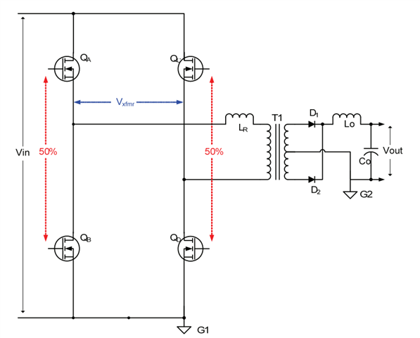
This thread has been locked.

If you have a related question, please click the "Ask a related question" button in the top right corner. The newly created question will be automatically linked to this question.

TMS320F28379D: Phase-shifted PWM issue

Part Number: TMS320F28379D


Tool/software:

I have generated the phase-shifted PWMs of 100kHz for Phase-shifted Full bridge application.

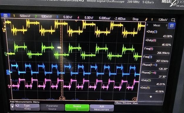
during testing in open loop, at 100V hv input to PSFB, the phase-shifted PWM pins' frequency change to 200kHz.

This was not observed at lower voltages of 60V and 80V.

the PSFB is rated for 320V (nominal), 2.5KW.

Here are the images for reference:
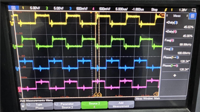
PWM QA is Yellow

PWM QB is Green

PWM QC is Blue

PWM QD is Pink

PWMs at 60V:

PWM at 100V:

  • Hello,

    The switching frequency/period is changing based on TBPRD ePWM register. Unless you have modified it in your ISR, it should not change by itself once initialized correctly.

  • Hello Stevan,

    No modification in code. It's just by changing input HV from 60V to 100V

  • Hello,

    Possible causes for that could be that your dead-time is dependent on voltage somehow. The dead time between the phase-shifted PWM signals might be decreasing as the input voltage increases. This could be due to the voltage-dependent characteristics of the gate drivers, power MOSFETs, or the control circuitry. As the dead time decreases, the effective frequency of the PWM signals might increase.

    Other possible reason I can think of is magnetic core saturation. The high-frequency transformer or inductor in the PSFB might be saturating at higher input voltages, causing the PWM frequency to increase. This could be due to the increased magnetic flux density or the core material's non-linear behavior.

    To verify this phenomenon, investigate the dead time. Measure the dead time between the phase-shifted PWM signals at different input voltages to see if it's decreasing as the voltage increases.
    Check the magnetic core. Verify that the magnetic core is not saturating at higher input voltages. You can measure the core's magnetic flux density or use a core loss simulator to predict its behavior.
    Perform a thorough analysis: Use simulation tools, such as SPICE or a dedicated power electronics simulator, to model the PSFB converter and investigate the potential causes of the frequency doubling.

    Additional questions:
    Have you measured the input voltage and current at 100V to ensure that the converter is operating within its rated specifications?
    Are there any changes in the converter's temperature or thermal management at higher input voltages that could be affecting the PWM frequency?
    Have you tried adjusting the dead time or other control parameters to see if it affects the PWM frequency at higher input voltages?

  • Hello Stevan,

    We are generating 4 PWMs; PWM_1A, PWM_1B, PWM_2A, PWM_2B.

    We kept same configuration for both ePWM modules, except that the PWM_2A and PWM_2B are phase-shifted with respect to PWM_1A and PWM_1B.

    And we are facing this issue with only the PWM_2A and PWM_2B.

    In the ePWM modules, we are keeping frequency constant and giving duty ratio and phase-shift via CAN.

    Since we are not selecting any dead-time, there shouldn't be any change.


    Answer for mentioned questions:

    Yes, we are measuring input voltage and current, which is within the rated specifications.

    No, there is no change in the temperature as load is very minimal 1%.

    No, we are not changing dead-time, the frequency is constant, while the duty ratio and phase-shift is given via CAN.

  • Hello,

    Thank you for your reply. Could you provide me with more details on how you generate you phase shift, please? Do you use TBPHS register, what is your sync-in and sync-out etc?