Tool/software:
Hi TI Tech Expert,
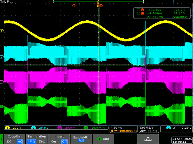
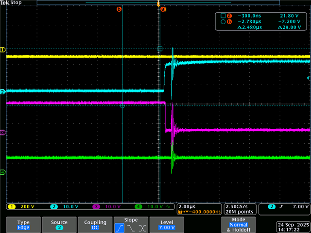
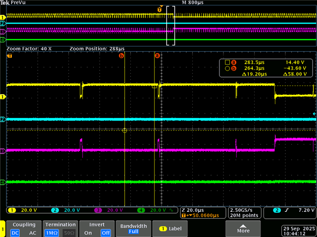
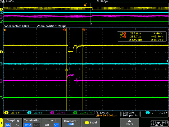
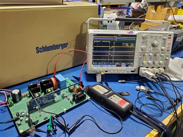
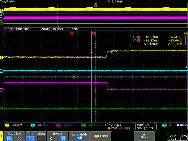
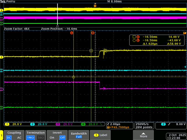
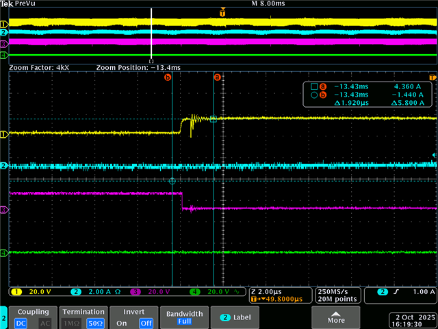
I am running some of tests on TIDM-HV-1PH-DCAC eval system. I ran this system as voltage source inverter in Open Loop mode. The system works as expected. However, I noticed that there are spikes on all 4 gate control signals (i.e. Q1.PWM, Q2.PWM, Q3.PWM, and Q4.PWM). I have a big concern on these spikes that may create the "shoot through" condition and damage the switching devices (MOSFET or IGBT). Can anyone explain why these spikes are present and how to suppress them if possible. The attached picture show the spikes probed on TP15 (ch2), TP16 (ch3), and TP20 (ch4) on the eval board. Thanks for any reply.