This thread has been locked.

If you have a related question, please click the "Ask a related question" button in the top right corner. The newly created question will be automatically linked to this question.

TMS320F28P550SJ: PWM CTR=ZERO interrupt trigger time jitter

Part Number: TMS320F28P550SJ

Tool/software:

Hi Expert

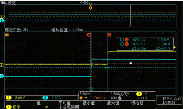
Customer feedback they find the PWM CTR=ZERO interrupt trigger delay is not fix. the test method is, they set AQ block PWM set high when CTR = ZERO, at the same time, set a GPIO high in PWM CTR=ZERO interrupt, and find the rising edge interval between the 2 output is different in each trigger:

  • you can see the 1st interval is 186ns:

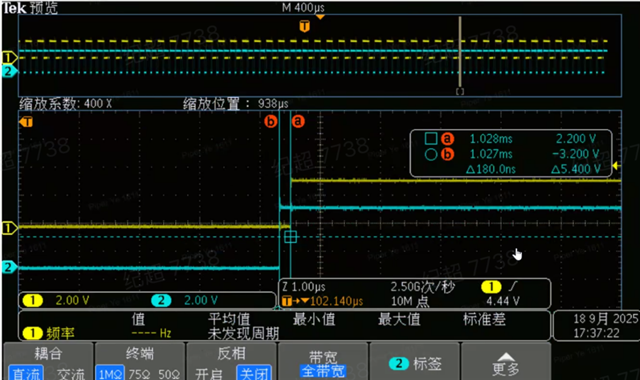
  • the 2nd interval is 180ns

  • there is another 400ns interval but no picture feedback.

there is only PWM interrupt in the code, no other interrupt that blocks the PWM interrupt:

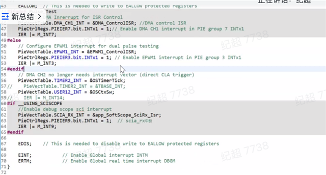
Could you please kindly help to look into why this interval happen and why there is the jitter in the time interval?

Thanks

Joe

  • Hi Expert 

    could you please help to look into this issue?

    thanks

    Joe

  • Joe,

    These two settings are not guaranteed to sync with each other because one is set in hardware (ePWM) and other set in ISR using software (GPIO). Once ePWM triggers ISR, there is latency in context saving and entering ISR and then setting GPIO so these timing can vary each cycle a bit. If you want these two things synced you will have to find hardware connection to do it not through software.

    Regards,

    Sumit

  • Hi Sumit

    Thanks for your reply, and sorry for the delay due to vacation. This test is not to sync the PWM output to GPIO, it just a test for the interrupt latency, so could you please help to explain why the interrupt latency is different? and what's the best case (minimum interrupt latency), and worst case (maximum interrupt latency)?

    Thanks

    joe

  • Joe,

    Please refer the following e2e post explaining your scenario:  Understanding C2000 Interrupt Latency 

    In general, for internal interrupt there is 14 cycle latency and external is 16 cycle. That is around 100ns just for interrupt. After that GPIO writing using API will add that time. The minimum latency can increase substantially depending on the current state of the CPU and other system factors: 

    • Disabled interrupts (INTM): The C2000 automatically disables further interrupts upon entering an ISR. If interrupts are also manually disabled in the main code, any incoming interrupt will be delayed until interrupts are re-enabled.
    • Multi-cycle instructions: The CPU must complete any currently executing instruction, including multi-cycle ones, before it can process an interrupt. Instructions like the RPT (repeat) loop cannot be interrupted at all.
    • Memory wait states: If code or the stack is being accessed from slower, wait-stated memory (like flash or external memory), the latency increases because the CPU cannot process the interrupt until the memory access is complete.
    • Inefficient code: A long and inefficient main loop can delay interrupts. Using an idle instruction asm(" IDLE"); when the CPU has nothing else to do is one way to ensure it is in a consistent, interrupt-ready state.
    • Interrupt priority: The C2000 has a Peripheral Interrupt Expansion (PIE) block that prioritizes interrupts. A lower-priority interrupt will be delayed if a higher-priority one is being serviced.
    • ISR complexity: The hardware latency only accounts for the time to reach the first instruction of your ISR. The total response time includes any instructions needed to save and restore registers and the time for the ISR to execute.
    • External pin qualification: For external interrupts, any debouncing or qualification logic applied to the input pin will add additional delay

    Regards,

    Sumit

  • Hi Sumit

    Thanks for your reply, the long delay time of PWM interrupt (~400us) is caused by the previous interrupt time out.

    Best regards

    Joe